1-10 Introduction
Hitachi Compute Rack 220H CRU Replacement Guide
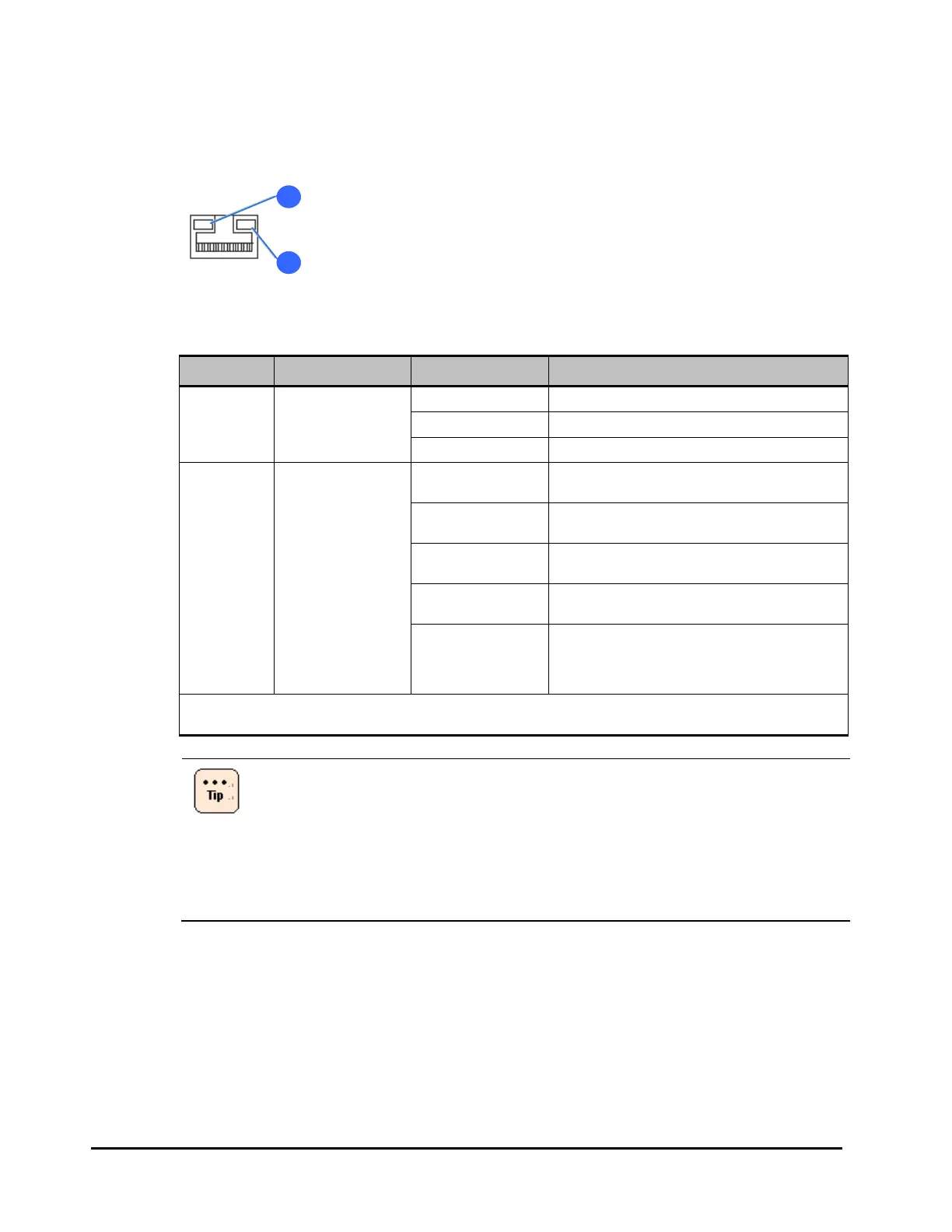
Network interface connectors 1, 2
The status LEDs on the connector are explained as follows.
Figure 1-7: Network interface connector status LED
Table 1-8: Network interface connector status LED indicate
Location Name State Description
1 Activity LED
Green-On
A link with a HUB has been established.
Green-Blink
Data is being transmitted or received.
Off
A link with a HUB has not been established.
2 Link LED
Amber-On*
A 1000BASE-T link with a hub has been
established.
Green-On*
A 100BASE-TX link with a hub has been
established.
Amber-Blink
A 1000BASE-T link with a hub is being
established.
Green-Blink
A 100BASE-TX or 10BASE-T link with a hub is
being established.
Off
A 10BASE-T link with a hub has been
established or link with a hub has not been
established.
The Activity LED shows either case.
* AC power is still supplied even if the power of the system unit is turned off, but this LED will be turned
off because only link by 10BASE-T can be established.
• Onboard LAN controllers (network interfaces) displayed by the
device manager are as follows:
– Onboard LAN1: PCI bus 8, device 0, function 0
– Onboard LAN2: PCI bus 8, device 0, function 1
• The number of the network adapter which is the network interface
connector recognized by the device manager may not match to the
network interface connector number.

 Loading...


