22
3. OPERATION PROCEDURE [How to Use the Liquid Crystal Display (LCD)]
When the schedule is selected, the AUTO light comes ON
(glowing) if the time setting is valid and ON (blinking) if
the time setting is invalid. The settings can be memorized
while the air compressor is stopped.
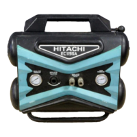
㼇 㻿㻯㻴㻱㻰㼁㻸 㻱 㻌 㻿㻱㼀㼀 㻵 㻺㻳 㼉
㻝㻥䠖㻜㻣
㻝䠊㻹㻻㻰㻱 䠖 㻯㻴㻱㻰㼁㻸㻱
㻿㼀㻭㻾㼀 㻿㼀
㻿
㻻㻼
䠄㻝䠅㻜㻣䠖㻜㻜㻌 㼅 㻞㻜䠖㻜㻜㻌 㼅
䠄㻞䠅㻜㻜䠖㻜㻜㻌 㻺 㻜㻜䠖㻜㻜㻌 㻺
䠄㻟䠅㻜㻜䠖㻜㻜㻌 㻺 㻜㻜䠖㻜㻜㻌 㻺
䠄㻠䠅㻜㻜䠖㻜㻜㻌 㻺 㻜㻜䠖㻜㻜㻌 㻺
䠄㻡䠅㻜㻜䠖㻜㻜㻌 㻺 㻜㻜䠖㻜㻜㻌 㻺
㻞䠊㻾㻱㻯㻻㻾㻰 㻝䠖 㻝㻜䠖㻜㻜
㻟䠊㻾㻱㻯㻻㻾㻰 㻞䠖 㻝㻥䠖㻜㻜
㻿㻱㼀䠖㻿㼀㻻㻾㻱 㻌㻹㻻㻺䠖㻮㻭㻯㻷
Allows a standard daily scheduling operation.
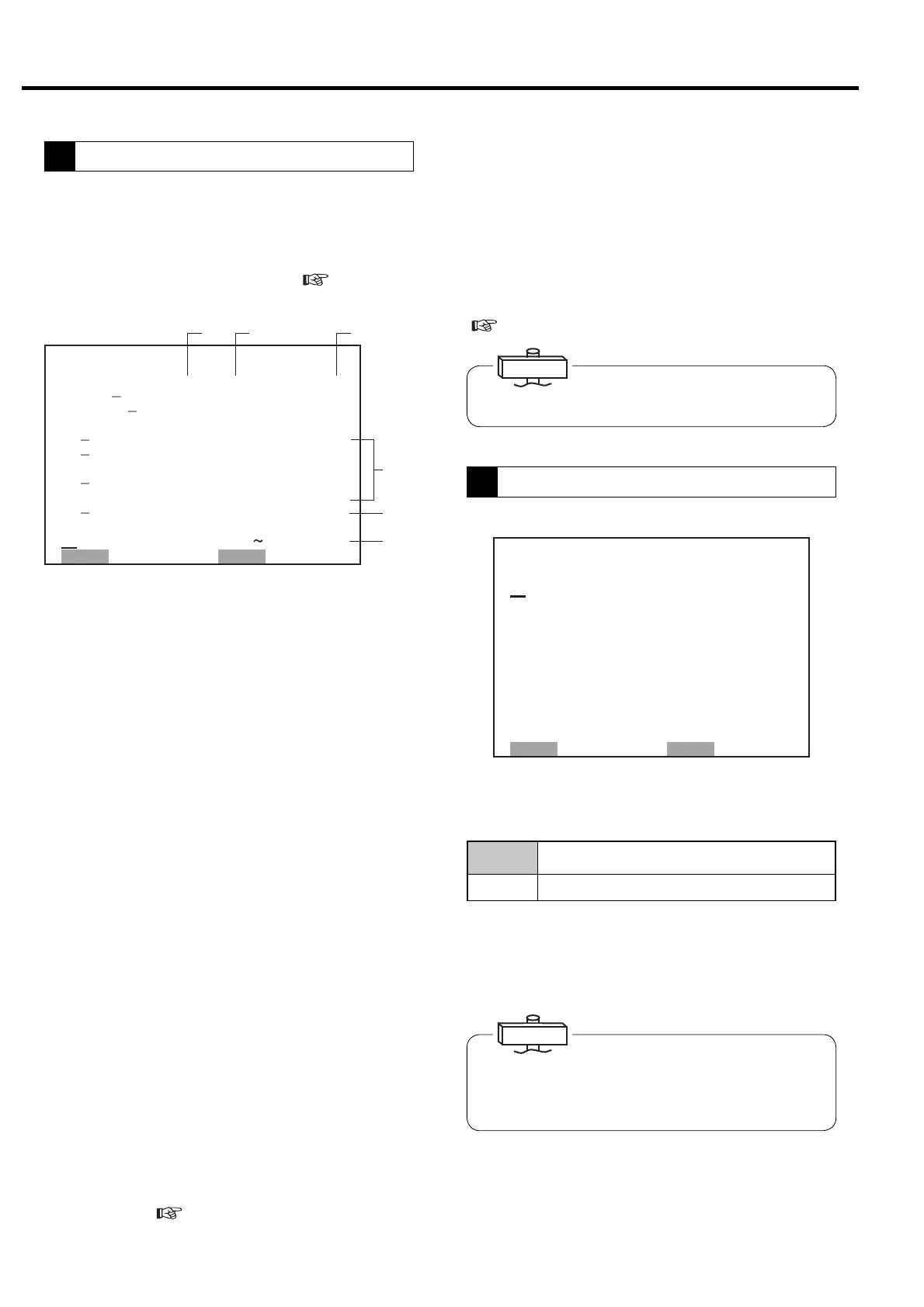
1. Type: Indicates the setting data for capacity control
①
Type of capacity control (Cannot be changed from LCD
monitor)
Fixed speed type
I: Indicates the standard, 2-step control.
IP: Indicates the optional motor stop/restart capacity
control to “I”.
Vtype
VA: Indicates motor stop/restart capacity control is
effective.
VB: Indicates motor stop/restart capacity control is
canceled.
② Pressure setting (Cannot be changed from LCD
monitor)
S-1: Indicates pressure setting 1
S-2: Indicates pressure setting 2
EXT: Indicates external pressure setting
S-A : Indicates pressure setting switches by set time
on
⑥.
③ Option condition and setting.
NUL: Indicates no option.
2. - 3. OPTION: Used for options.
4. - 6. Pressure Setting: ④ Indicates cut-in, cut-out
and target pressure setting 1 and 2 can be confirmed.
Target means target pressure for ECOMODE
7. TIME LIMIT (Fixed speed type only)
⑤ Indicates the time limit of load/unload one-cycle time
for ECOMODE. Load/unload one-cycle time must be 30
second or more. (
3.4.8)
(1) to (5) : Five Start/Stop Time Patterns
・ START : Starting Time
・ STOP : Stopping Time
・ Y or N : Yes starts or stops as scheduled.
2.-3. RECORD1, 2 : This function allows for the
capability to record data over a desired time in a day. To
view the recorded data, refer to “5. Operation data
display” on the next page.
IMPORTANT
1. MODE:
OFF Operates without a schedule.
Schedule Operates according to a daily 24- hour calendar.
This illustration indicates a scheduling operation from 7:00 to
20:00. TIME field indicates a current time of 19:07.
①② ③
④
⑤
⑥
㪲 㪚㪦㪥㪫㪩㪦㪣 㪪 㪜 㪫㪫 㪠 㪥㪞 㪴
㪈䋮㪫㪰㪧㪜䋺㪭㪘 㪪㪄㪈 㪥㪬㪣
㪉䋮䌐
㪣㪦㪪㪪䋺 㪁 㪁 㪁㫇 㫊 㫀
㪊䋮䌐 㪠
㪚㪘䋺㪁㪁㪁 㪁㪁䋮㪁䌭㪊
䋨㪚㪦㪥㪫㪩㪦㪣䋯㪚㪬㪫㪄 㪠 㪥 㪀
㪋
㪧㪈䋺 㪈㪇㪉䋯 㪏㪎㫇㫊㫀
㪌
㪧㪉䋺 㪈㪇㪉䋯 㪏㪎㫇㫊㫀
䋨㪫㪘㪩㪞㪜㪫㩷㪧㪈䋯㪧㪉 㪀
㪍
㪫㪘㪩㪞㪜㪫䋺
㪐㪌䋯 㪐㪌㫇㫊 㫀
㪎
㪫㪠㪤㪜㩷㪣㪠㪤㪠㪫䋺 㪇㪊㪇㫊
䋨㪧㪉 㪜㪝㪝㪜㪚㪫 㪠 㪭㪜 㪀
㪏䋮㪫㪠㪤㪜䋺㪈㪏䋺 㪇㪇
㪉㪉䋺㪇㪇
㪪㪜㪫䋺㪪㪫㪦㪩㪜 㩷㪤㪦㪥䋺㪙㪘㪚㪢
8. TIME:⑥ Can set the time to use pressure setting 2.
When set the value properly, ② is indicated in “ S-A”. If
the start and stop time is set at same value, pressure
setting 2 is not in use and ② is indicated in S-1. And
pressure setting 1 and 2 can be change by external
switch. Set the F018 on digital monitor “2”.
(
3.4.2 , 3.4.7)
The settings can be memorized while the air compressor
is stopped.
IMPORTANT
This function sets the pressures and times for capacity
control. Two different combinations (P1 and P2) of
pressures can be used. Item number with dot “ . ” can be
select from LCD monitor. Item number with a dash “ - “
can be selected from digital monitor. (
3.4 How to
Use the Digital Monitor for the detail.)
3
Capacity control
4
Scheduled Operation

 Loading...