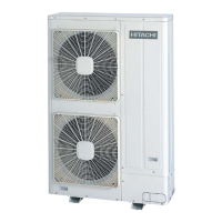
Connection diagram: heat pump system
A
A1
B
TB1
3N
400V/50Hz
1N
220-240V/50Hz
230V/50Hz
3N
400V/50Hz
TB1 TB2
L1 L2 L3 N 1 2 3 4
TB2
1 2 3 4
TB1
L1 L2 L3 N
1 2 A B
TB2
1 2 A B
TB2
TB1
L1 L2 N L1 L2 N
ELB
ELB
ELB
C C
D
D
E E
F
F
F
G G
H I
CB
CB
CB
ELB
ELB
ELB
J
A Main outdoor unit
A1 Secondary outdoor unit
B Operation wiring (shielded twisted pair cable or shielded pair cable) 5 Vdc non-polar H-LINK (field-supplied)
C Distribution box (field-supplied)
D Indoor units
E Operation wiring (shielded twisted pair cable or shielded pair cable) (field-supplied)
F Fuse (field-supplied)
G PC-ART remote control
H Indoor unit system No 0
I Indoor unit system No 1
J Transmission wire between A and A1
CB Circuit breaker (field-supplied)
ELB Earth Leakage Breaker (field-supplied)
4 Electrical wiring
77
SMGB0065 rev. 1 - 12/2010
4

 Loading...


