S1 series standard inverter
-97-
Detailed parameter description
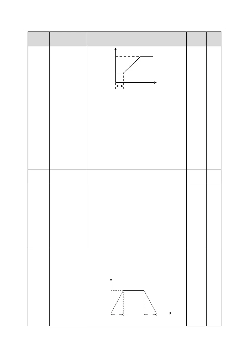
Hold time of
starting frequency
Output frequency
fmax
t1
T
F1 set by P01.01
f1
T1 set by P01.02
A proper starting frequency can increase the
torque during startup. Within the hold time of
starting frequency, the output frequency of
inverter is the starting frequency, and then it runs
from the starting frequency to the target
frequency, if the target frequency (frequency
command) is below the starting frequency, the
inverter will be standby rather than running. The
starting frequency value is unlimited by the lower
limit frequency.
Setting range: 0.0–50.0s
DC brake current
before start
During starting, the inverter will first perform DC
brake based on the set DC brake current before
startup, and then it will accelerate after the set DC
brake time before startup elapses. If the set DC
brake time is 0, DC brake will be invalid.
The larger the DC brake current, the stronger the
brake force. The DC brake current before startup
refers to the percentage relative to rated inverter
current.
Setting range of P01.03: 0.0–100.0%
Setting range of P01.04: 0.00–50.00s
DC brake time
before start
Acceleration/dece
leration mode
This function code is used to select the frequency
variation mode during starting and running.
0: Straight line; the output frequency increases or
decreases in straight line;
fmax
Output frequency f
t1 t2
Time t
1: S curve; the output frequency increases or

 Loading...


