EasyManuals Logo

Hitachi S1 Series User Manual

Hitachi S1 Series
235 pages
To Next Page IconTo Next Page
To Previous Page IconTo Previous Page
Page #231 background imageLoading...
Page #231 background image
S1 series standard inverter
-226-
PB
External brake resistor
+
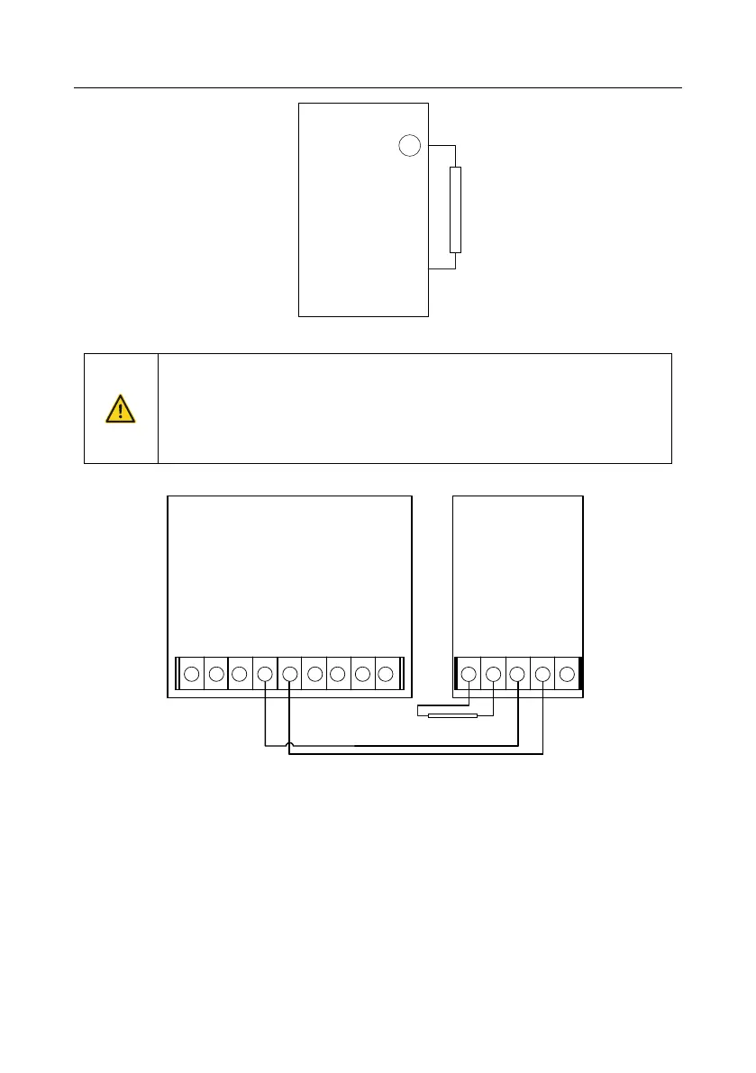
Installation of brake units
(+) and (-) are the terminals for connecting brake units.
The connection cables between the (+) and (-) terminals of an inverter and
those of a brake unit must be shorter than 5 m, and the connection cables
between the BR1 and BR2 terminals of a brake unit and the terminals of a
brake resistor must be shorter than 10 m.
The following figure shows the connection of one inverter to a dynamic brake unit.
External brake resistor
DBU
brake
unit
(+)
DC+
(-)
DC-
BR1 BR2
(-)
PE
(-)
+ + + + + + + + +
+ + + + +

Table of Contents

Questions and Answers:

Question and Answer IconNeed help?

Do you have a question about the Hitachi S1 Series and is the answer not in the manual?

Hitachi S1 Series Specifications

General IconGeneral
Output Frequency0 - 400 Hz
Overload Capacity150% for 60 seconds
Frequency50/60 Hz
Control MethodSensorless Vector Control
Protection FunctionsOvercurrent, Overvoltage, Undervoltage, Overheat, Short Circuit
CommunicationRS485, Modbus RTU
Output Voltage3-Phase 200-240VAC, 3-Phase 380-480VAC (Matches Input Voltage)
Cooling MethodFan Cooled

Related product manuals