S1 series standard inverter
-25-
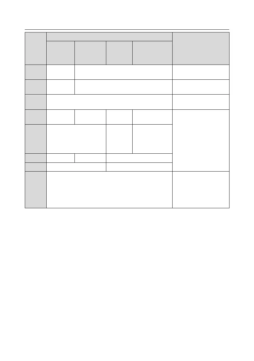
1PH AC input terminal,
connect to the grid
3PH AC input terminal,
connect to the grid
3PH AC output terminal,
connect to the motor
P1 and (+) connect to
external DC reactor
terminal
(+) and (-) connect to
external brake unit terminal
PB and (+) connect to
external brake resistor
terminal
Brake resistor terminal 1
DC reactor
terminal 2,
Brake unit terminal
1
Brake resistor terminal 2
Grounding resistor is less than 10 ohm
Grounding terminal for safe
protection; each machine
must carry two PE
terminals and proper
grounding is required
Note:
1. Do not use asymmetrical motor cable. If there is a symmetrical grounding conductor in the motor
cable besides the conductive shielded layer, ground the grounding conductor on the inverter end
and motor end.
2. Brake resistor, brake unit and DC reactor are optional parts.
3. Route the motor cable, input power cable and control cables separately.
4. "Null" means this terminal is not for external connection.
5. "/" means this terminal doesn’t exist.
4.3.3 Wiring process of the main circuit terminals
1. Connect the grounding line of the input power cable to the grounding terminal (PE) of the
inverter, and connect the power input cable to L, N (230V) or R, S and T (400V) terminals and
tighten up.
2. Connect the grounding line of the motor cable to the grounding terminal of the inverter, and
connect 3PH motor cable to U, V and W terminals and tighten up.
3. Connect the brake resistor which carries cables to the designated position.
4. Fix all the cables outside the inverter mechanically if allowed.
 Loading...


