S1 series standard inverter
-30-
Keypad portUSB port
R02 AR01 A
+1 0VAI2AI1HD IBHD IAS4S3S2S1
GN DAO1Y1HD OCOMPW
R02 BR01B
+2 4VH1
R02 CR01C
H2PE CO MCO M 485 G485 -CME+2 4V 485 +
+2 4V
U-type short-
contact tag of H1
and +24V
U-type short-
contact tag of
PW and COM
U-type short-contact
tag of COM and
+CME
U-type short-
contact tag of H2
and +24V
Fig 4.20 Position of U-type short-contact tag
Note: As shown in Fig 4.19, the USB port can be used to upgrade the software, and the keypad port
can be used to connect an external keypad. The external keypad cannot be used when the keypad of
the inverter is used.
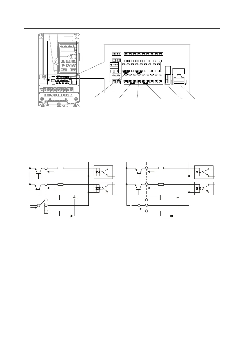
If input signal comes from NPN transistors, set the U-type short-contact tag based on the power used
according to the figure below.
S1
S2
COM
PW
+
24V
COM
+ 24V
Internal power(NPN mode)
S1
S2
COM
PW
+ 24V
COM
+
24V
External power(NPN mode)
+ 24V
Fig 4.21 NPN mode
If input signal comes from PNP transistor, set the U-type short-contact tag based on the power used
according to the figure below.
 Loading...


