S1 series standard inverter
-78-
Detailed parameter description
HDIB terminal switch-off delay
Input terminal state of present
fault
Digital input terminal state
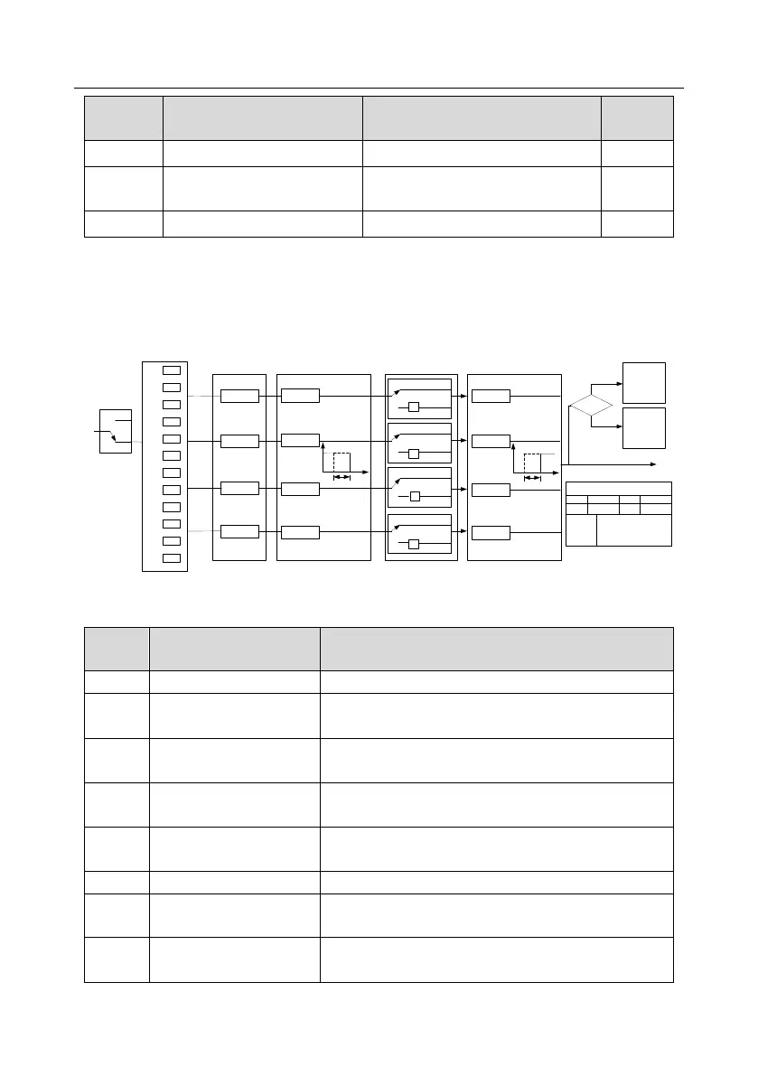
5.5.11 Digital output
S1 series inverter carries two groups of relay output terminals, one open collector Y output terminal
and one high-speed pulse output (HDO) terminal. The function of all the digital output terminals can
be programmed by function codes, of which the high-speed pulse output terminal HDO can also be
set to high-speed pulse output or digital output by function code.
0
1
2
3
4
5
.
.
.
.
29
30
P06.01
P06.03
P06.04
P06.02
T delay
T delay
T delay
T delay
0
1
P06.05 output polarity
selection
(Default value: 0)
(Default value: 0)
(Default value: 1)
(Default value: 5)
P06.00
HDO
input type
0
1
0
1
0
1
delay
0
1
-1
-1
-1
-1
P17.12
Digital input
terminal state
P07.40
Digital output
terminal state
of current fault
Fault?
Fault
Run
Y BIT0 HDO BIT1
ROI BIT2 RO2 BIT3
P06.05, P17.12, P07.40 display
P06.00
0: Open collector high-
speed pulse output
1: Open collector output
P06.07
P06.09
P06.11
P06.13
Y
RO2
ROI
HDO
Digital switch-off delay
Digital output selection
T delay
T delay
T delay
T delay
delay
P06.06
P06.08
P06.10
P06.12
Digital switch-on delay
The table below lists the options for the above four function parameters, and users are allowed to
select the same output terminal functions repetitively.
Output terminal has no function
Output ON signal when there is frequency output during
running
Output ON signal when there is frequency output during
forward running
Output ON signal when there is frequency output during
reverse running
Output ON signal when there is frequency output during
jogging
Output ON signal when inverter fault occurred
Frequency level detection
FDT1
Refer to P08.32 and P08.33
Frequency level detection
FDT2
Refer to P08.34 and P08.35

 Loading...