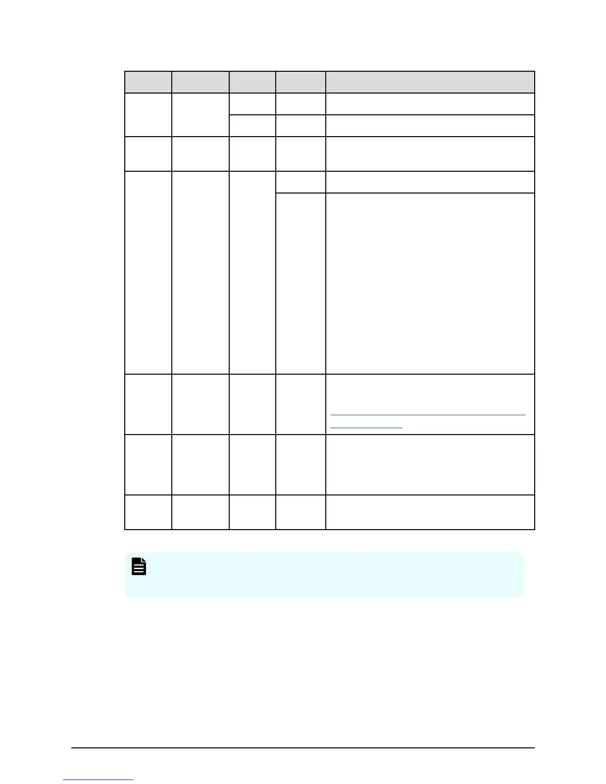
Number Item Color Pattern Description
1 POWER
LED
Green ON Storage system is powered on.
Amber ON Storage system is receiving power.
2 READY
LED
Green ON Storage system is ready for normal
operation.
3 WARNING
LED
Amber ON Component requires maintenance.
Blink Failure occurred. Requires maintenance.
When the SIM is conrmed, the LED
pattern indicates the failure and requires
attention.
Note: When System Option Mode 1097 is
set to ON, the WARNING LED does not
blink, even if the following failure service
information messages (SIM) are issued:
452xxx, 462xxx, 3077xx, 4100xx, and
410100.
LED might turn o during user
maintenance.
4 ALARM
LED
Red ON Processor failure (system might be down).
For assistance, contact customer support:
https://support.hitachivantara.com/en_us/
contact-us.html.
5 POWER
ON/OFF
(main
switch)
- - Turns on power to the storage system.
6 Lock - - Locks and unlocks the front panel bezel by
using the supplied key.
Note: Removing a controller can cause the POWER, READY, WARNING, and
ALARM LEDs on the front panel to turn o. These LEDs return to their on
state after the storage system recovers from the controller replacement.
The following table describes the denitions of the CBSL controller front panel LEDs
without an attached front bezel.
Controller chassis with large form-factor drive bays (CBSL)
Chapter 2: Hardware components and specications
Hitachi Virtual Storage Platform G130 Hardware Reference Guide 29

 Loading...