Number Item Description
• Indicates the location of the
chassis.
• Can be turned on or turned
off by the maintenance
utility.
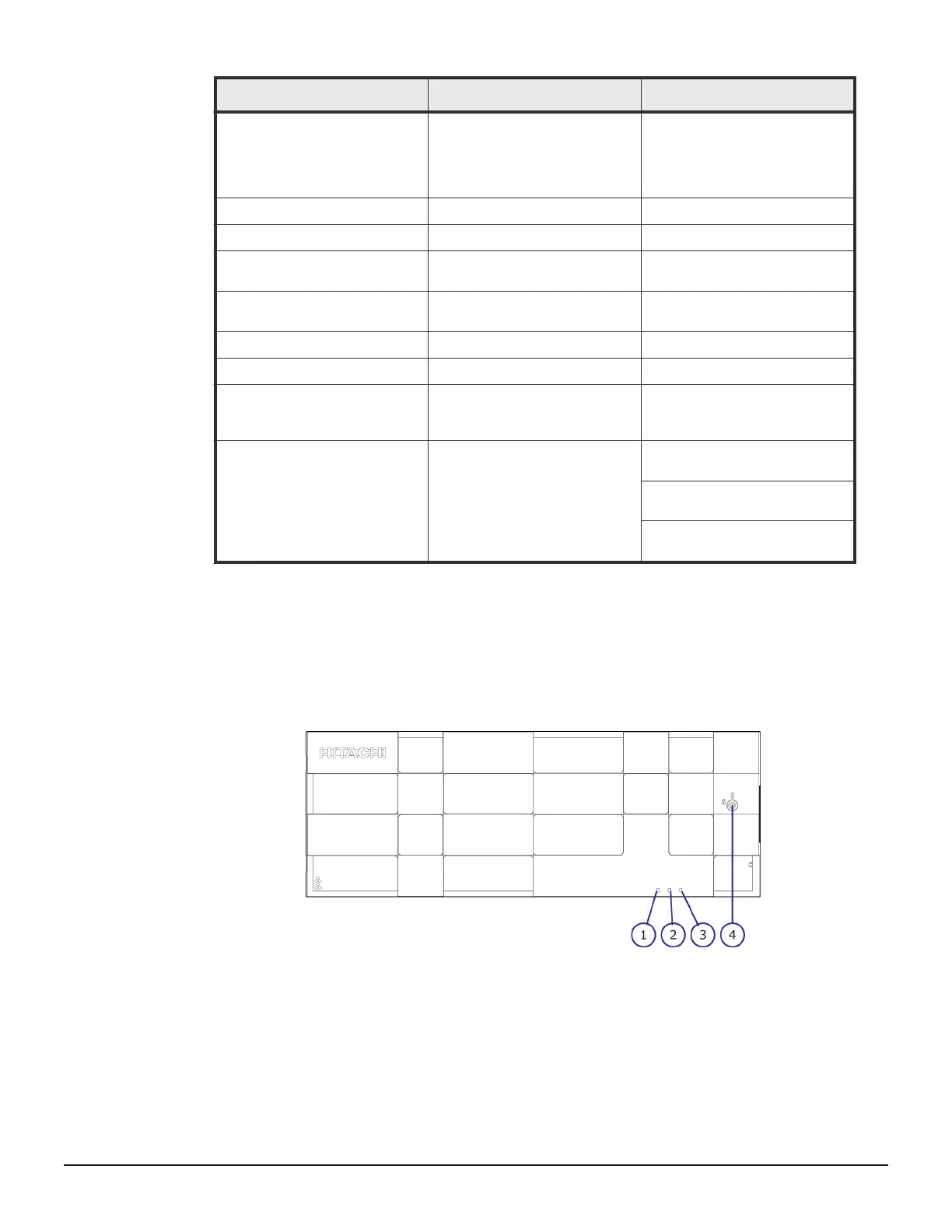
4
ALARM LED Red: ENC can be replaced.
5
PATH (IN) LED Blue: IN side port is linked up.
6
PATH (IN) connector Connects to a controller or
drive tray.
7
PATH (OUT)LED Blue: OUT side port is linked
up.
8
PATH (OUT) connector Connect to a drive tray.
9
Console This port is reserved.
10
Receptacle Connects to the power cable
provided with the storage
system.
11 Three LEDS, top to bottom:
RDY LED
AC IN LED
ALM REPLACE LED
Green: Power supply unit is
operating normally.
Green: Power supply unit is
operating normally.
Red: Power supply unit can be
replaced.
Dense intermix drive tray
Dense intermix drive tray with front panel bezel
50 Storage system drive trays
Hitachi Virtual Storage Platform G400, G600 Hardware Reference Guide