Number
Description
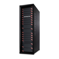
1
LEDs. From left to right, the LEDs are:
• BMC Heartbeat
• LAN card 2
• LAN card 1
• Hard drive
• System standby power
2
Reset button.
3
Power button. Applies power to or removes
power from the SVP.
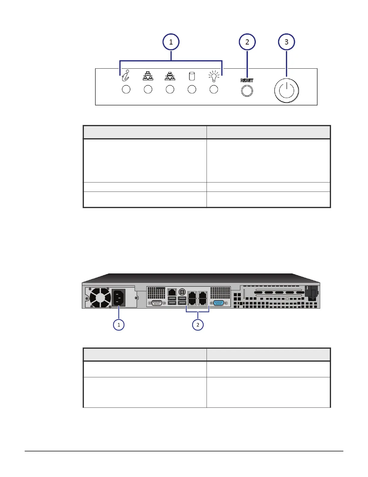
SVP rear panel
The only ports used on the rear panel of the physical SVP are the power
socket and the four LAN ports.
Number
Description
1
Power socket. Attach the power cable supplied
with the SVP.
2
Four LAN ports arranged as follows:
LAN3 LAN4
LAN1 LAN2
VSP service processor server 63
Hitachi Virtual Storage Platform G400, G600 Hardware Reference Guide