User Manual Installation, Assembly and Commissioning
EM1 Series AC Servo Motors EM1-01-0-EN-2110-MA Page 41 of 72
8.2 Servo Motor Installation
8.2.1 Mechanical
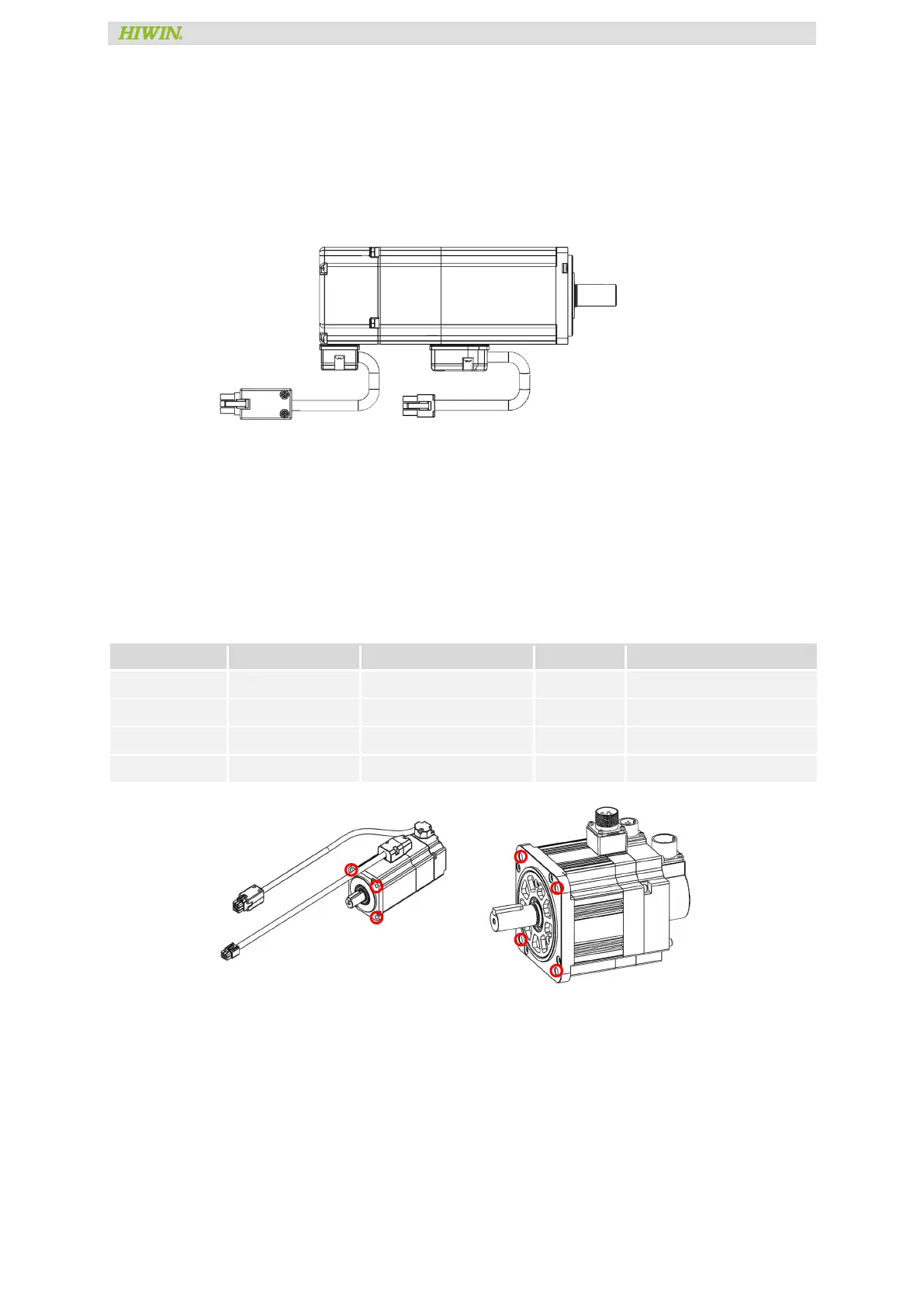
8.2.1.1 Motor
Orientation
1. Horizontal: cable lead must face downward to prevent oil or water penetration.
2. Vertical direction: when the motor shaft mounted with reducer is installed facing
upwards, oil seal must be used to prevent the reducer oil from flowing into the inside
of the motor.
Installation Interface
The motor rated specifications (rated output, rated torque, and rated speed) are the continuous
allowable values at an ambient temperature of 40°C (from 40 to 50 de-rating avoid
condensation and icing) when servo motors are installed with the following heat sinks and
screws.
(1 Nm = 10,1972 kgfcm)
Motor PCD screw hole (mm) Interface(mm) Screw Type Tightening Torque
200x200x6, aluminum plate
1,63 Nm (16,6 kgfcm)±10 %
200 W to 400 W 5,5 250x250x6, aluminum plate 4*M5x20
3,28 Nm (33,4 kgfcm)±10 %
750 W 6,6 250x250x6, aluminum plate 4*M6x20
5,58 Nm (56,9 kgfcm)±10 %
1 kW to 2 kW 9 400x400x20, iron plate 4*M8x20
13,5 Nm (138 kgfcm)±10 %
Protective Structure
HIWIN servo motor protective structure is described below.
– 50 W to 750 W: IP65
Except for power connector, encoder connector, motor through shaft section need to add oil
seal which is optional for all type of AC servo motor.
 Loading...