User Manual Appendix
EM1 Series AC Servo Motors EM1-01-0-EN-2110-MA Page 66 of 72
Legend table „Motion Profile“
1 Acceleration time
2 Deceleration time
3 Stop time
4 Cycle time
5 Constant-velocity time
6 Travel distance (shaded area)
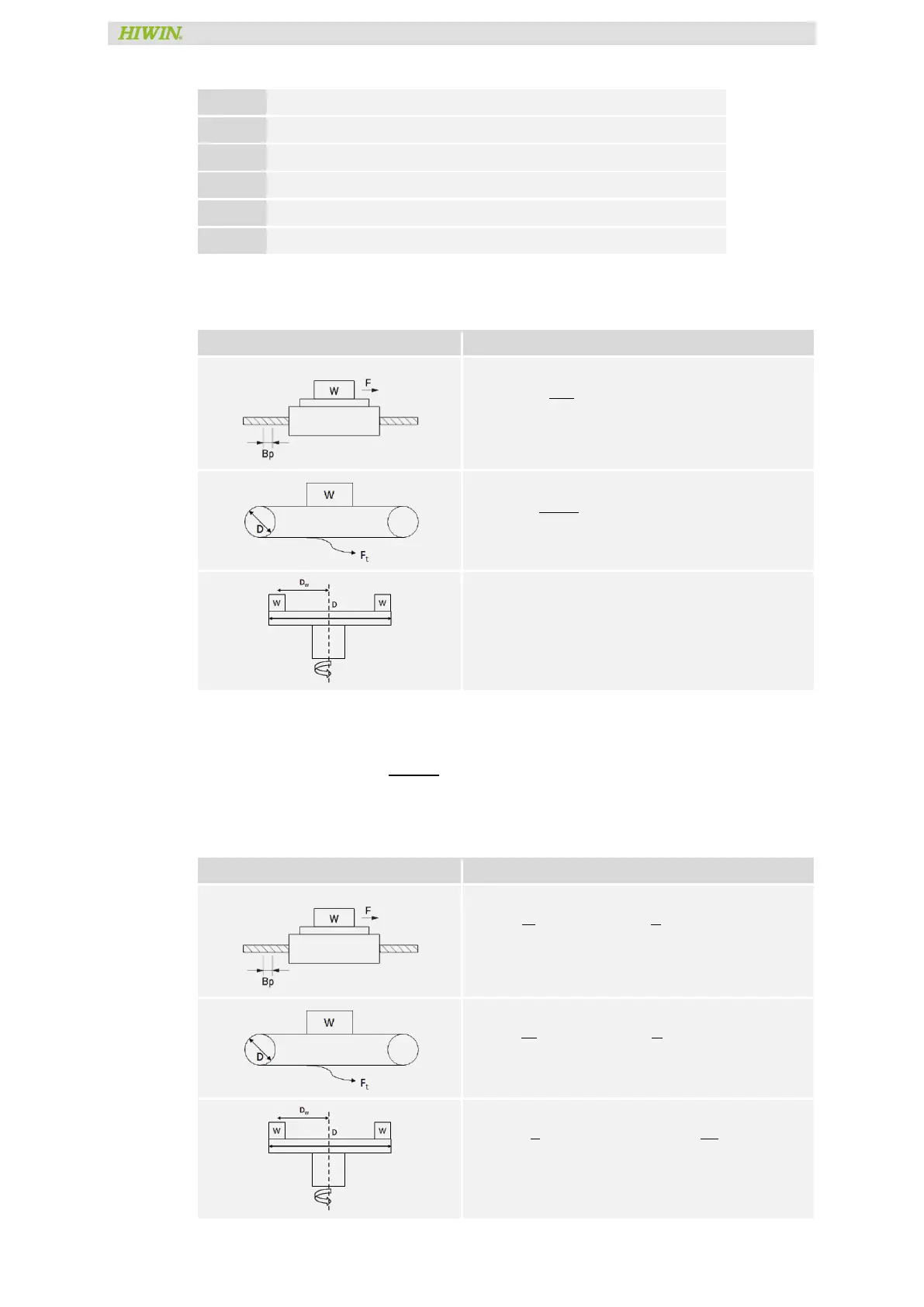
13.1.3 Load Inertia Calculation
Transmission mechanism Load inertia calculation
Ball Screw
J
= J
+
WB
B
: Ball screw lead (m)
Pulley & Belt
J
= J
+
W × D
4
Rotary Table
J
= J
+ n × (J
+ WD
)
(Continuing contents of previous page)
Load inertia ratio suggested bellowing 30 times of normal operation
=
(
+
)
<
13.1.4 Motor Speed Calculation
Transmission mechanism Motor speed calculation
Ball Screw
N =
V
B
× 60 V velocity (
m
s
)
Pulley & Belt
N =
V
D
× 60 V velocity (
m
s
)
Rotary Table
N =
× 30 angular velocity (
rad
s
)
 Loading...