OM-260 274 Page 10
SECTION 3 − DEFINITIONS
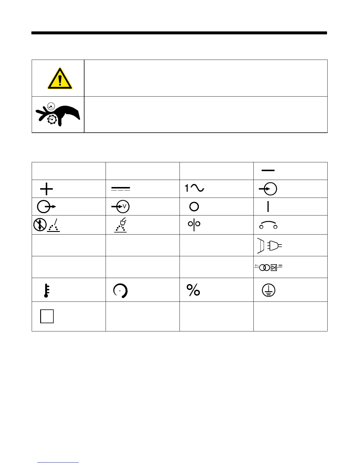
3-1. Additional Safety Symbols And Definitions
. Some symbols are found only on CE products.
Warning! Watch Out! There are possible hazards as shown by the symbols.
Safe1 2012−05
Drive rolls can injure fingers.
Safe32 2012−05
3-2. Miscellaneous Symbols And Definitions
. Some symbols are found only on CE products.
A
Amperage
V
Voltage
Hz
Hertz Negative
Positive
Direct Current
(DC)
Single Phase Input
Output Voltage Input Off On
Do Not Switch
While Welding
Gas Metal Arc
Welding (GMAW)
Wire Feed Circuit Protector
U
0
Rated No Load
Voltage (Average)
U
1
Primary Voltage
U
2
Conventional Load
Voltage
Line Connection
I
1max
Rated Maximum
Supply Current
I
2
Rated Welding
Current
X
Duty Cycle
Single Phase
Transformer-
Rectifier
Temperature Increase Percent
Protective Earth
(Ground)
S
Suitable For
Welding In An
Environment With
Increased Risk Of
Electric Shock
I
1
Rated Supply
Current
I
1eff
Maximum Effective
Supply Current

 Loading...