. A complete Parts List is available at www.HobartWelders.com
OM-260 274 Page 24
SECTION 6 − OPERATION
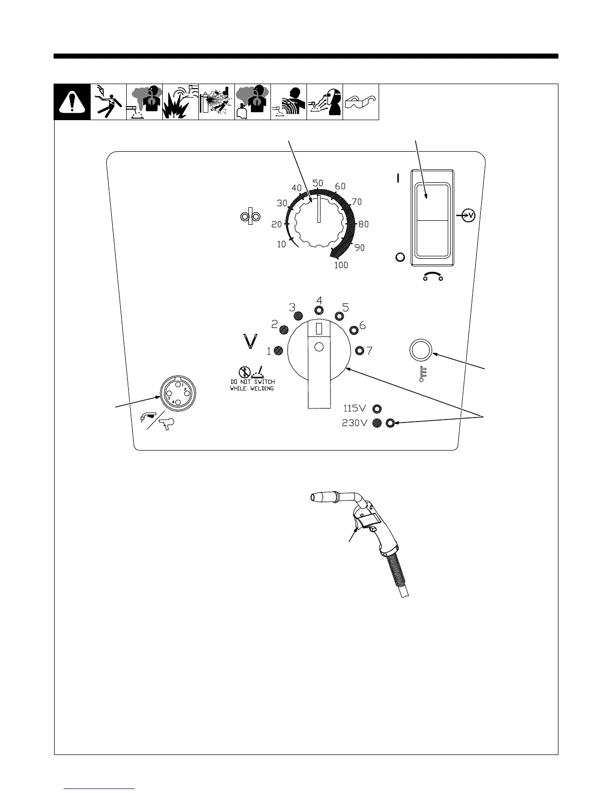
6-1. Controls
1 Wire Speed Control
Control varies the rate of wire being fed
through the welding gun.
2 Power Switch/Supplementary
Protector
Turns power on and off. Also, this switch
functions as supplementary protector CB1.
CB1 protects unit from overload. If CB1
opens, unit shuts down.
Reset power switch/supplementary
protector.
3 Voltage Control
Control varies the voltage level of the
welding arc. The voltage range is 4
(minimum) to 7 (maximum) on 115 VAC
and 1 (minimum) to 7 (maximum) on 230
VAC.
. Switch must “click” into detent
position. DO NOT switch under load.
4 Over Temperature Light
Light illuminates if main transformer
overheats.
5 Gun Trigger Receptacle
6 Trigger Switch
When pressed, energizes wire feed motor
and gas valve for shielding gas flow.
250 650-A
6
1
2
3
5
4

 Loading...