. A complete Parts List is available at www.HobartWelders.com
OM-260 274 Page 14
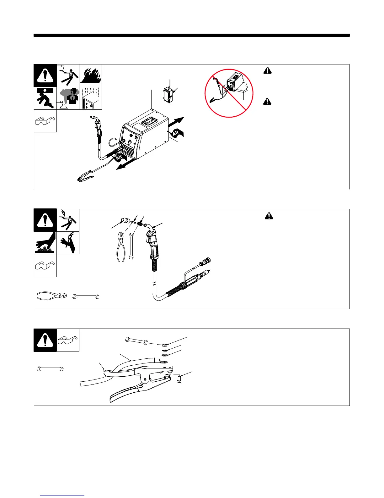
SECTION 5 − INSTALLATION
! Special installation may be
required where gasoline or
volatile liquids are present −
see NEC Article 511 or CEC
Section 20.
! Do not move or operate unit
where it could tip.
1 Line Disconnect Device
Locate unit near correct input power
supply.
5-1. Selecting A Location
1
18 in
(460 mm)
18 in
(460 mm)
Location And Airflow
250 3322-B / ST-139 445-E
5-2. Installing Nozzle, Contact Tip, And Adapter
Ref. 243 839-A
! Turn off welding power
source.
1 Nozzle
2 Contact Tip
3 Tip Adapter
. Wire size stamped on tip − check
and match wire size.
Tools Needed:
8 mm
Head
Tube
8 mm
1
3
2
5-3. Installing Work Clamp
258 550-A
1
2
3
4
5
6
1 Work Clamp
2 Work Cable From Unit
3 Screw
4 Flat Washer
5 Lock Washer
6 Nut
Route work cable through
hole in clamp handle. Secure
cable with hardware as
shown.
. Connection hardware
must be tightened with
proper tools. Do not just
hand tighten hardware.
A loose electrical
connection will cause
poor weld performance
and excessive heating of
the work clamp.
Tools Needed:
10 mm

 Loading...