15 of 20
Pump Start Relay Connection
L This controller does not provide mains power
to drive a pump–a pump must be driven via
an external relay and contactor setup.
L The controller provides a low voltage signal
that actuates the relay which in turn enables
the contactor and finally the pump
Although the controller has permanent memory and
thus a default program will not cause erroneous
valve actuation as in some controllers, it is still good
practice when using a system where the water
supply comes from a pump to connect unused
stations on the unit back to the last used station
This in effect, inhibits the chances of the
pump ever running against a closed head
Pump Protection (System Test)
L In some circumstances not all operational
stations may be hooked up–for example,
if the controller was capable of running 6
stations but there were only 4 field wires and
solenoid valves available for connection
This situation can pose a risk to a pump when the
system test routine for the controller is initiated
The system test routine sequences through
all available stations on the controller
In the above example this would mean stations
5 through to 6 would become active and would
cause the pump to operate against a closed head
This could possibly cause permanent
pump, pipe and pressure vessel damage
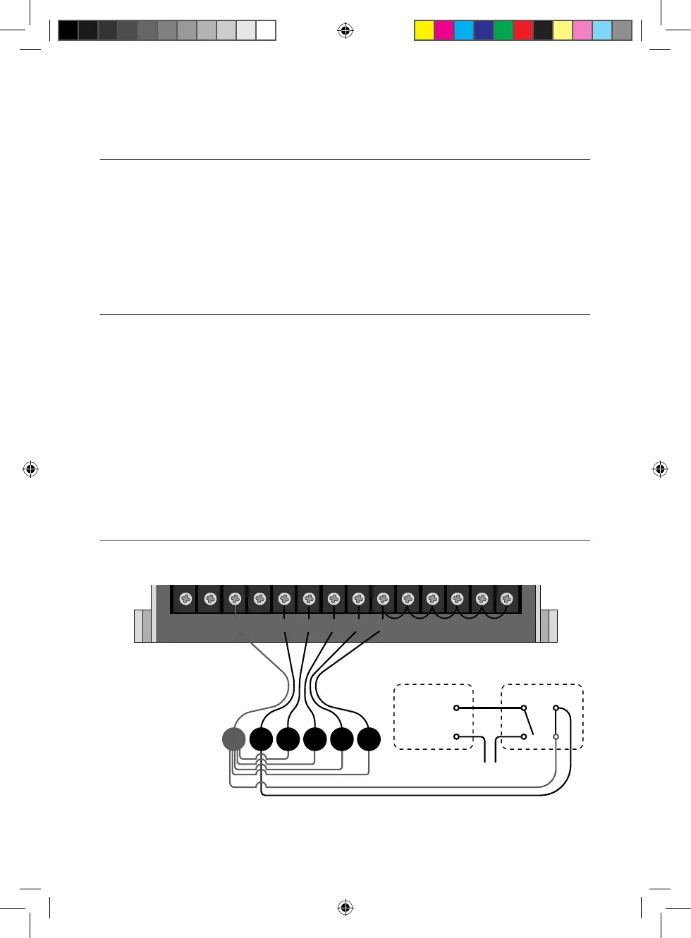
It is mandatory if the system test routine is going
to be used, that all unused, spare stations,
should be linked together and then looped to
the last working station with a valve on it
Using this example, the connector block
should be wired as per the diagram below
Single Phase Pump Installation
It is recommended to always use a relay between the controller and the pump starter
C 1 2 3 4
24VAC C R M 1 2 3 4 5 6 7 98
PUMP
MOTOR
MAGNETIC
STARTER
24VAC AC RELAY
POWER SUPPLY
M
Installation (continued)
PRO469 Manual 2021 v1.indd 15PRO469 Manual 2021 v1.indd 15 15/1/21 9:40 am15/1/21 9:40 am