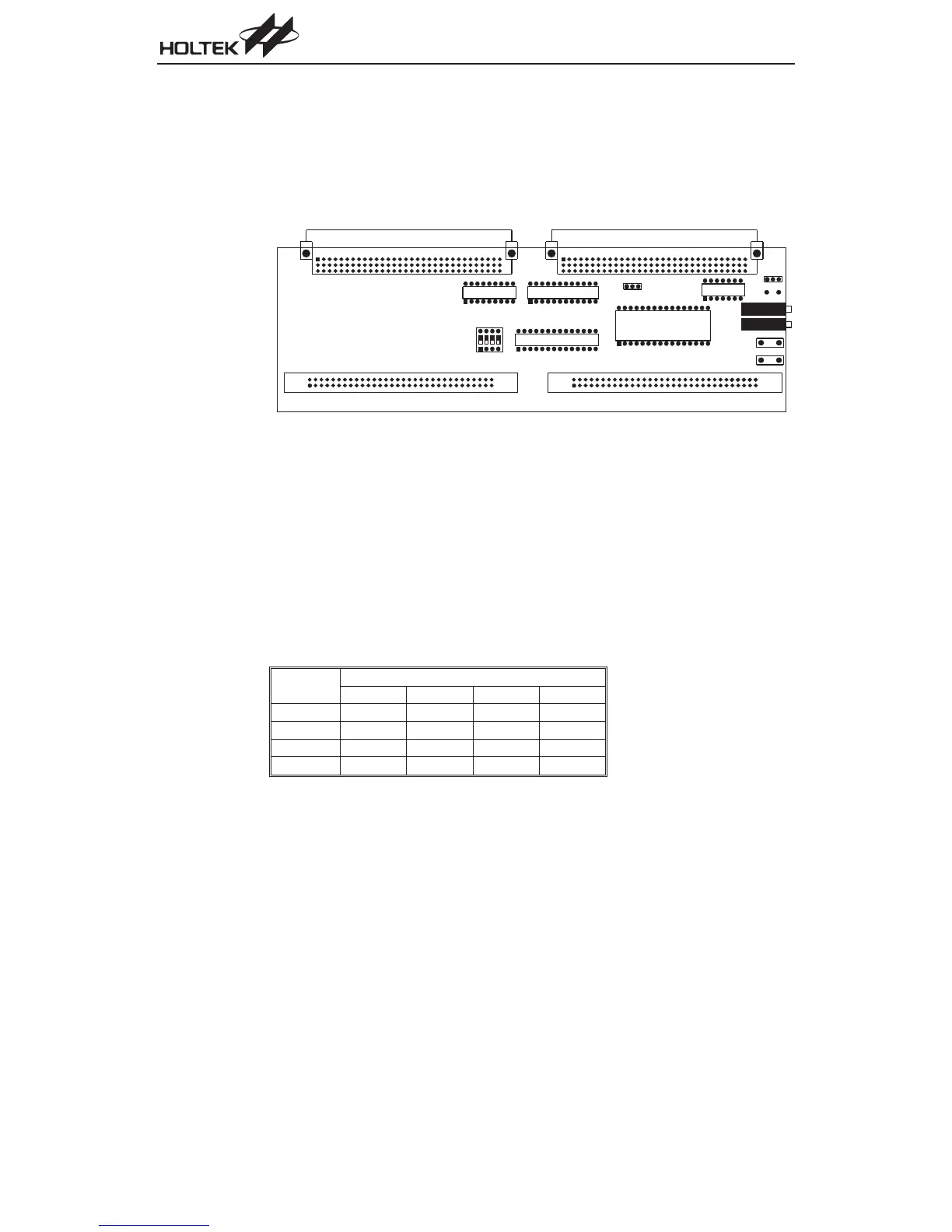
HT-ICE Interface Card Settings
The HT-ICE interface card (CPCB46SER0001A) as shown below, is a PCB used to connect the
HT-ICE emulator to user¢s target board. It has the following functions:
·
External clock source
·
A/D converter HTUY0001 in location U5
·
MCU socket pin assignment
The external clock source has two modes, RC and Crystal. If a crystal clock is used, short posi
-
tions 2 and 3 on Jumper JP1 and insert a suitable crystal into location Y1. Otherwise, if an RC
clock is used, short positions 1 and 2, then adjust the system frequency using VR1. Refer to the
Tools/Mask Option Menu of the HT-IDE3000 User¢s Guide for the clock source and system fre
-
quency selection.
Set the jumper JP2 to select the MCU¢s A/D converter AVDD power supply source. Short positions
1 and 2 on JP2 if the HT-ICE 5V supply voltage is to be used as the source. For other externally
supplied AVDD voltages, short positions 2 and 3, then provide the voltage from JP3 and JP4.
DIP switch SW1 should be set according to which device is selected and in accordance with the fol-
lowing table:
Part No.
SW1
1234
HT46R22
¾¾¾¾
HT46R23
¾¾¾¾
HT46R24 OFF OFF OFF OFF
HT46R47
¾¾¾¾
JP6 consists of the I/O ports and other pins. The MCU pin assignment in location U2, U3 and U4
are defined so as to match the datasheet pin assignment for the A/D series of MCUs. The interface
card VME connectors directly interface to the CN1 and CN2 connectors on the HT-ICE.
124
A/D Type MCU
J P 5
V R 2
J P 6
J P 1
J P 3
J P 4
J P 2
U 1
U 2
U 3
U 4
S W 1
U 5
V R 1
Y 1