System RC Oscillator
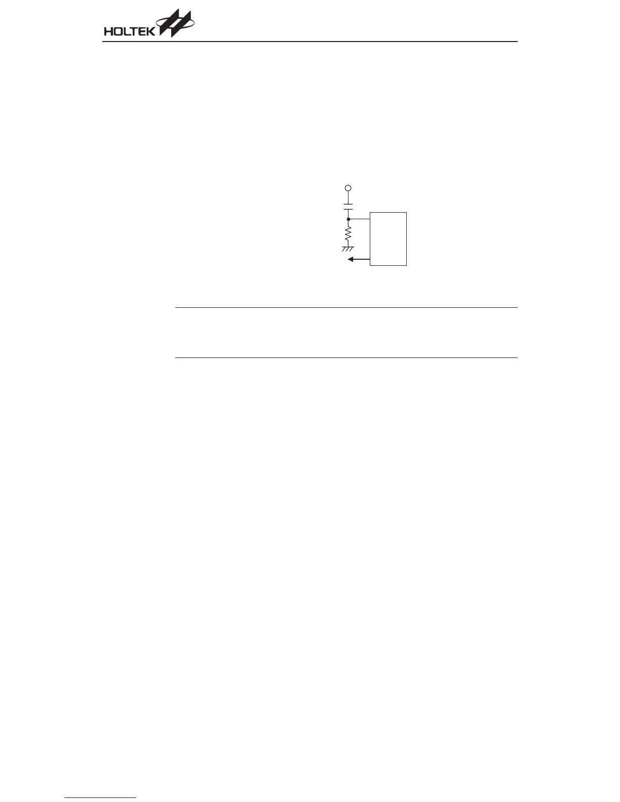
Using the external RC network as an oscillator requires that a resistor, with a value between 30kW
and 750kW, is connected between OSC1 and GND. The generated system clock divided by 4 will
be provided on OSC2 as an output which can be used for external synchronization purposes. Al
-
though this is a cost effective oscillator configuration, the oscillation frequency can vary with VDD,
temperature and process variations on the chip itself and is therefore not suitable for applications
where timing is critical or where accurate oscillator frequencies are required. For the value of the
external resistor R
OSC
please refer to the Appendix section for typical RC Oscillator vs. Tempera
-
ture and V
DD
characteristics graphics.
Note
An internal capacitor together with the external resistor, R
OSC
, are the components which deter
-
mine the frequency of the oscillator. The external capacitor shown on the diagram does not influ
-
ence the frequency of oscillation. This external capacitor should be added to improve oscillator
stability if the open-drain OSC2 output is utilized in the application circuit.
Watchdog Timer Oscillator
The WDT oscillator is a fully self-contained free running on-chip RC oscillator with a typical period
of 65ms at 5V requiring no external components. When the device enters the power down mode,
the system clock will stop running but the WDT oscillator continues to free-run and to keep the
watchdog active. However, to preserve power in certain applications the WDT oscillator can be dis-
abled via a configuration option.
HALT and Wake-up in Power Down Mode
The HALT mode is initialized by the ²HALT² instruction and results in the following:
·
The system oscillator will be turned off
·
The contents of the on chip RAM and registers remain unchanged
·
The WDT will be cleared and resume counting if the WDT clock source is selected to come from
the WDT oscillator
·
All of the I/O ports remain unchanged
·
The
PDF
flag is set and the TO flag is cleared
Chapter 1 Hardware Structure
73
O S C 1
O S C 2
f
S Y S
/ 4 N M O S O p e n D r a i n
4 7 0 p F
V
D D
R
O S C
RC Oscillator