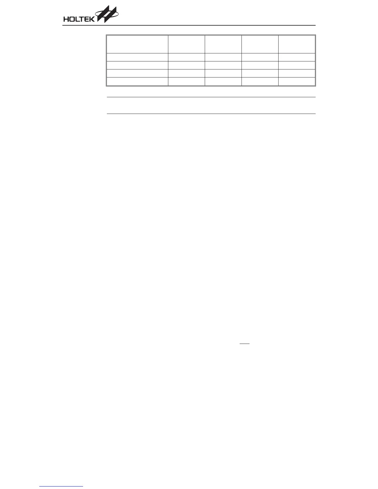
Interrupt Source
HT46R47
HT46C47
Priority
HT46R22
HT46C22
Priority
HT46R23
HT46C23
Priority
HT46R24
HT46C24
Priority
TMR/TMR0 Overflow 2222
TMR1 Overflow N/A N/A N/A 3
A/D Converter Interrupt 3334
I
2
C Bus Interrupt N/A 4 4 5
Note Only the HT46R24/HT46C24 devices have two internal timers, known as TMR0 and TMR1. The
other devices in the series have only one internal timer, which is known as TMR.
In cases where both external and internal interrupts are enabled and where an external and inter
-
nal interrupt occurs simultaneously, the external interrupt will always have priority and will there
-
fore be serviced first. Suitable masking of the individual interrupts using the INTC register can
prevent simultaneous occurrences.
Programming Considerations
The interrupt request flags, TF, T0F, T1F, EIF, ADF and HIF together with the interrupt enable bits
ETI, ET0I, ET1I, EEI, EADI and EHI form the interrupt control registers INTC, INTC0 and INTC1,
which are located in the Data Memory. By disabling the interrupt enable bits, a requested interrupt
can be prevented from being serviced, however, once an interrupt request flag is set, it will remain
in this condition in the INTC, INTC0 or INTC1 register until the corresponding interrupt is serviced
or until the request flag is cleared by a software instruction.
It is recommended that programs do not use the ²CALL subroutine² instruction within the interrupt
subroutine. Interrupts often occur in an unpredictable manner or need to be serviced immediately
in some applications. If only one stack is left and the interrupt is not well controlled, the original con-
trol sequence will be damaged once a ²CALL subroutine² is executed in the interrupt subroutine.
Reset and Initialization
A reset function is a fundamental part of any microcontroller ensuring that the device can be set to
some predetermined condition irrespective of outside parameters. The most important reset condi
-
tion is after power is first applied to the microcontroller. In this case, internal circuitry will ensure
that the microcontroller, after a short delay, will be in a well defined state and ready to execute the
first program instruction. After this power-on reset, certain important internal registers will be set to
defined states before the program commences. One of these registers is the Program Counter,
which will be reset to zero forcing the microcontroller to begin program execution from the lowest
Program Memory address.
In addition to the power-on reset, situations may arise where it is necessary to forcefully apply a re
-
set condition when the microcontroller is running. One example of this is where after power has
been applied and the microcontroller is already running, the RES
line is forcefully pulled low. In
such a case, known as a normal operation reset, some of the microcontroller registers remain un
-
changed allowing the microcontroller to proceed with normal operation after the reset line is al
-
Chapter 1 Hardware Structure
65