I
2
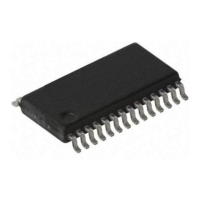
C Bus Slave Address Register - HADR
The HADR register is the location where the slave address of the microcontroller is stored. Bits
1~7 of the HADR register define the microcontroller slave address. Bit 0 is not implemented. When
a master device, which is connected to the I
2
C bus, sends out an address which matches the slave
address in the HADR register, the microcontroller slave device will be selected.
I
2
C Bus Input/Output Data Register - HDR
The HDR register is the I
2
C bus input/output data register. Before the microcontroller writes data to
the I
2
C bus, the actual data to be transmitted must be placed in the HDR register. After the data is
received from the I
2
C bus, the microcontroller can read it from the HDR register. Any transmission
of data to the I
2
C bus or reception of data from the I
2
C bus must be made via the HDR register.
I
2
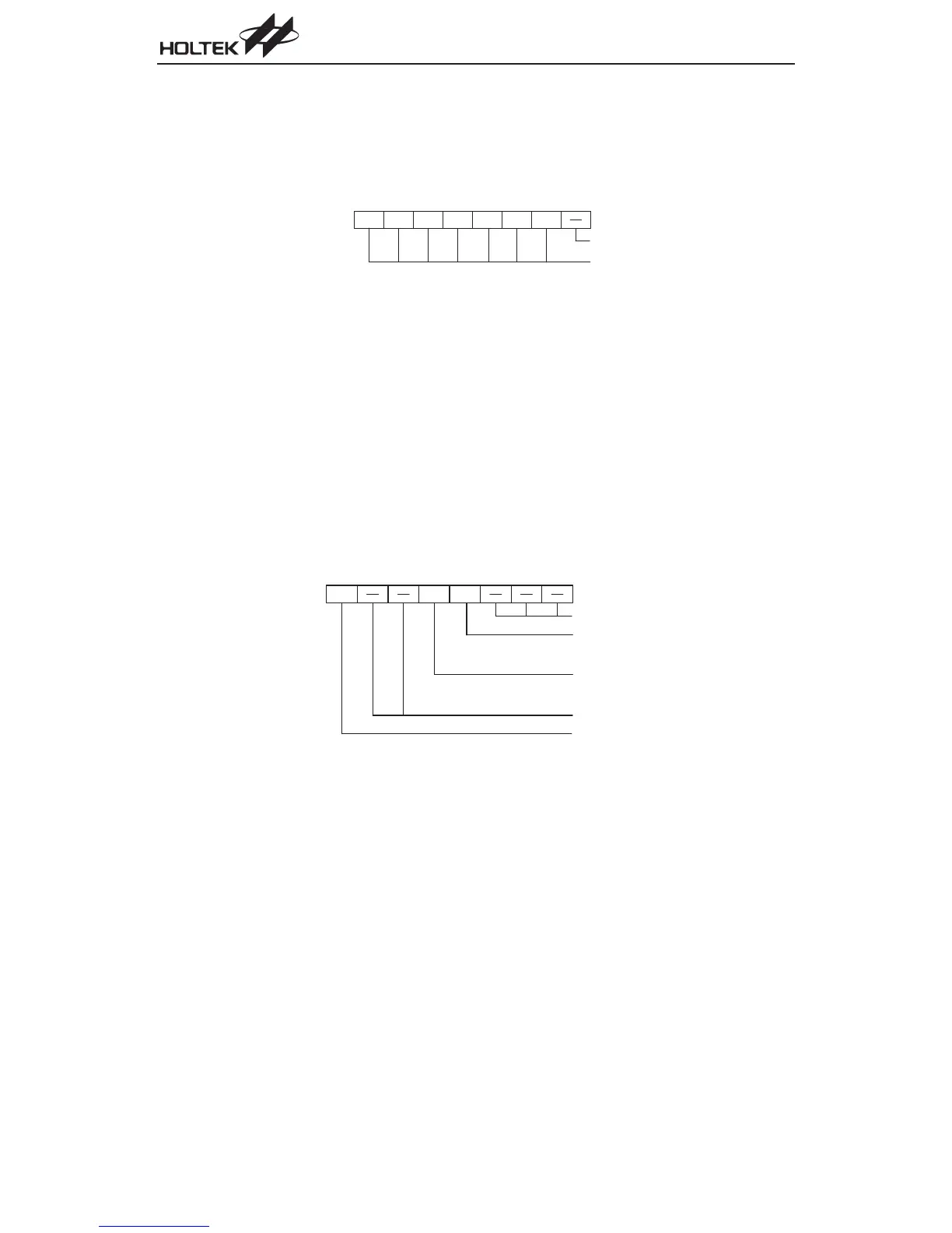
C Bus Control Register - HCR
The I
2
C bus control register HCR contains three bits. Bit 7, known as the HEN bit, determines if the
I
2
C bus function is enabled or disabled, this bit must be set if the I
2
C bus requires data transfer. Bit
4, known as the HTX bit, determines whether the device is in the transmit mode or receive mode,
and must be set high if the device is to be setup as a transmitter. Bit 3, known as the TXAK bit, is
the transmit acknowledge bit. After the receipt of 8 bits of data, this bit will be transmitted to the I
2
C
bus on the 9th clock. To continue receiving more data, this bit has to be reset to ²0² before more
data is received.
I
2
C Bus Status Register - HSR
The I
2
C bus register HSR is an 8-bit status register in which five bits are utilized. Bit 7, known as
HCF, is set to ²0² when a data byte is being transferred, after completion of the data transfer the bit
will be set to ²1². The HAAS bit, which is bit 6, will be set to ²1² if the transmitted address and the
slave address of the device match and if the I
2
C interrupt request flag is set to ²1². If the interrupts
are enabled and the stack is not full, a subroutine call to 10H will occur. Writing data to the I
2
C bus
Chapter 1 Hardware Structure
55
0 + 4 4 A C E I J A H
b 7 b 0
N o t i m p l e m e n t e d , r e a d a s " 0 "
T r a n s m i t a c k n o w l e d g e f l a g
1 : d o n ' t a c k n o w l e d g e
0 : a c k n o w l e d g e
T r a n s m i t / r e c e i v e m o d e
1 : t r a n s m i t m o d e
0 : r e c e i v e m o d e
N o t i m p l e m e n t e d , r e a d a s " 0 "
I
2
C B u s f u n c t i o n
1 : e n a b l e
0 : d i s a b l e
H E N T X A K
H T X
0 ) , 4 4 A C E I J A H
b 7 b 0
N o t i m p l e m e n t e d , r e a d a s " 0 "
S l a v e a d d r e s s