Oscillator
Various oscillator options offer the user a wide range of functions according to their various applica
-
tion requirements. Two types of system clocks can be selected while various clock source options
for the Watchdog Timer are provided for maximum flexibility. All oscillator options are selected
through the configuration options.
System Clock Configurations
There are two methods of generating the system clock, using an external crystal/ceramic oscilla
-
tor or an external RC network. The chosen method is selected through the configuration options.
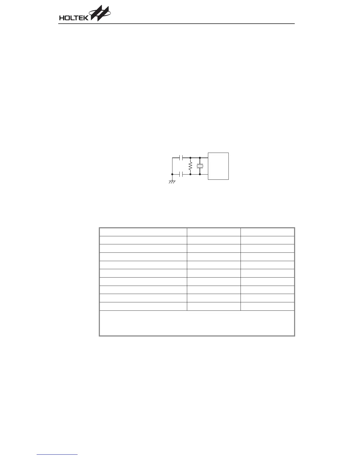
System Crystal/Ceramic Oscillator
For the crystal oscillator configuration, the simple connection of a crystal across OSC1 and OSC2
will create the necessary phase shift and feedback for oscillation with no other external compo
-
nents required. A ceramic resonator can be used instead of a crystal but two small value capaci
-
tors should be connected between OSC1, OSC2 and ground.
The table below shows the C1, C2 and R1 values for various crystal/ceramic oscillating frequen-
cies.
Crystal or Resonator C1, C2 R1
4MHz Crystal 0pF
10kW
4MHz Resonator 10pF
12kW
3.58MHz Crystal 0pF
10kW
3.58MHz Resonator 25pF
10kW
2MHz Crystal & Resonator 25pF
10kW
1MHz Crystal 35pF
27kW
480kHz Resonator 300pF
9.1kW
455kHz Resonator 300pF
10kW
429kHz Resonator 300pF
10kW
The function of the resistor R1 is to ensure that the oscillator will switch off should low voltage
conditions occur. Such a low voltage, as mentioned here, is one which is less than the lowest
value of the MCU operating voltage. Note however that if the LVR is enabled then R1 can be re
-
moved.
72
A/D Type MCU
O S C 2
O S C 1
C 2
C 1
R 1
Crystal/Ceramic Oscillator