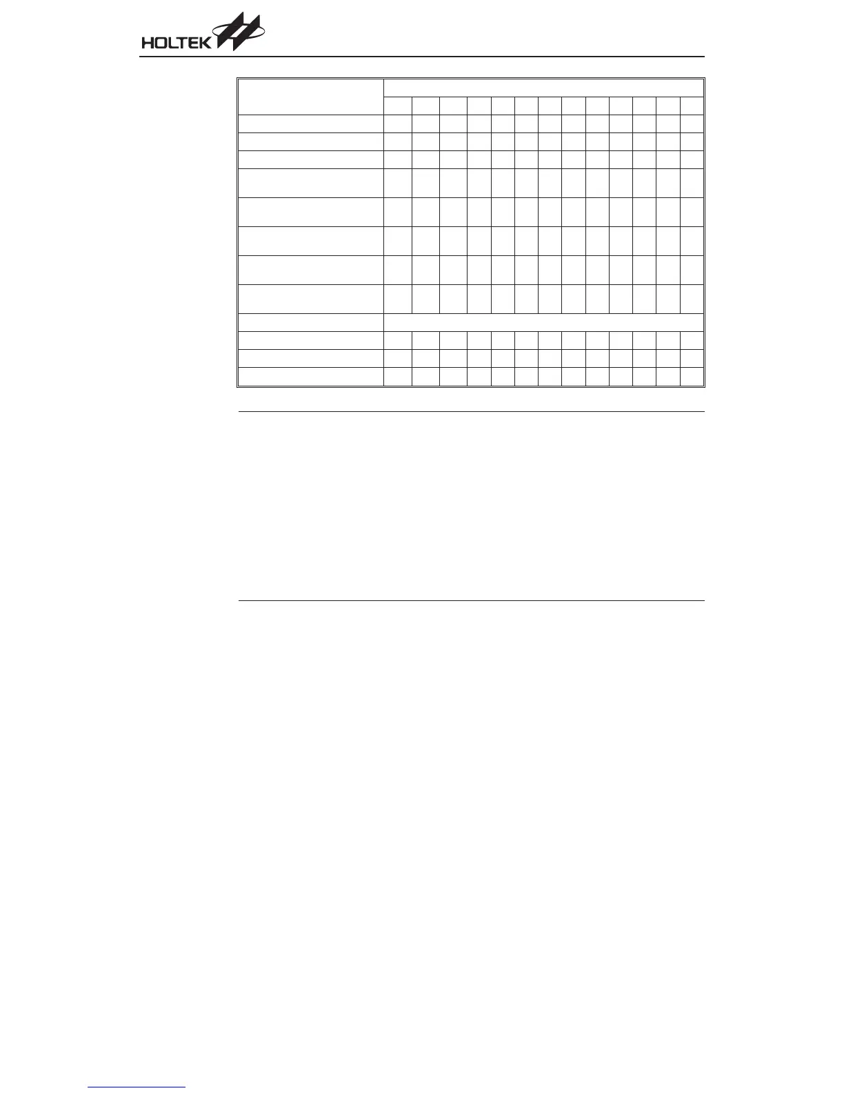
Mode
Program Counter Bits
b12 b11 b10 b9 b8 b7 b6 b5 b4 b3 b2 b1 b0
Initial Reset 0 0 0 0000000000
External Interrupt 0 0 0 0000000100
Timer/Event Counter 0 Overflow 0 0 0 0000001000
Timer/Event Counter 1 Overflow
(HT46R24/HT46C24 only)
0 0 0 0000001100
A/D Converter Interrupt
(except HT46R24/HT46C24)
0 0 0 0000001100
A/D Converter Interrupt
(HT46R24/HT46C24 only)
0 0 0 0000010000
I
2
C Bus Interrupt
(except HT46R24/HT46C24)
0 0 0 0000010000
I
2
C Bus Interrupt
(HT46R24/HT46C24 only)
0 0 0 0000010100
Skip Program Counter + 2
Loading PCL PC12 PC11 PC10 PC9 PC8 @7 @6 @5 @4 @3 @2 @1 @0
Jump, Call Branch #12 #11 #10 #9 #8 #7 #6 #5 #4 #3 #2 #1 #0
Return from Subroutine S12 S11 S10 S9 S8 S7 S6 S5 S4 S3 S2 S1 S0
Note 1. PC12~PC8: Current Program Counter bits
2. @7~@0: PCL bits
3. #12~#0: Instruction code bits
4. S12~S0: Stack register bits
5. For the HT46R24/HT46C24, the Program Counter is 13 bits wide, i.e. from b12~b0.
6. For the HT46R23/HT46C23, since its Program Counter is 12 bits wide, the b12 column in the
table is not applicable.
7. For the HT46R47/HT46C47, HT46R22/HT46C22, since its Program Counter is 11 bits wide,
the b11 and b12 columns in the table are not applicable.
8. The Timer/Event Counter 1 Overflow row is available only for the HT46R24/HT46C24.
9. For the HT46R47/HT46C47, HT46R22/HT46C22 and HT46R23/HT46C23 the Timer/Event
Counter 0 represents the single timer, known as TMR.
Chapter 1 Hardware Structure
17