The following table indicates the way in which the various components of the microcontroller are af
-
fected after a power-on reset occurs.
Item Condition After RESET
Program Counter Reset to zero
Interrupts All interrupts will be disabled
WDT
Clear after reset, WDT begins counting
Timer/Event Counter All Timer Counters will be turned off
Prescaler
The Timer Counter Prescaler will be cleared
Input/Output Ports All I/O ports will be setup as inputs
Stack Pointer Stack pointer will point to the top of the stack
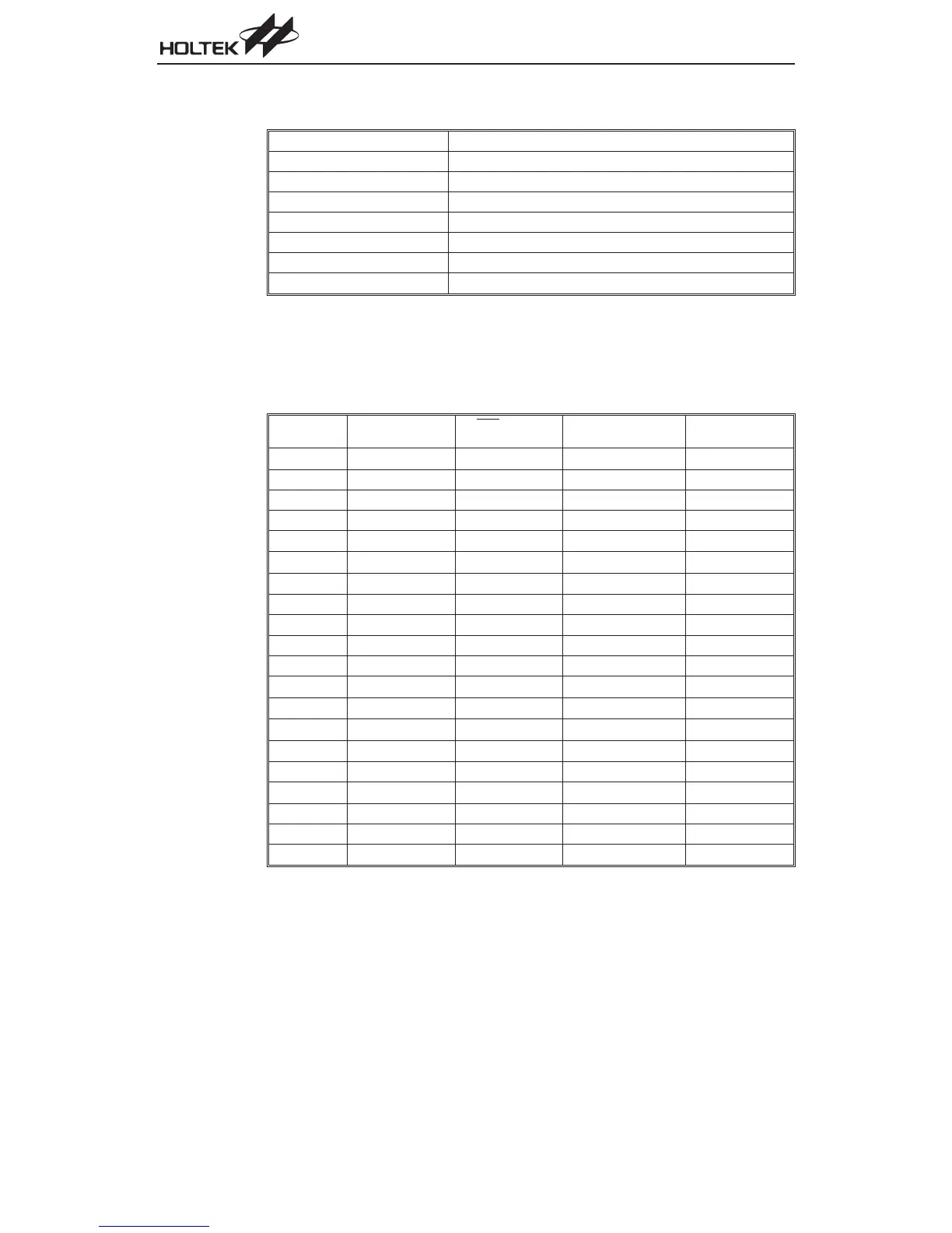
The different kinds of reset all affect the internal registers of the microcontroller in different ways.
To ensure reliable continuation of normal program execution after a reset occurs, it is important to
know what condition the microcontroller is in after a particular reset occurs. The following table de
-
scribes how each type of reset affects each of the microcontroller internal registers.
HT46R47/HT46C47
Register
Reset
(Power On)
RES
or LVR
Reset
WDT
Time-out
(Normal Operation)
WDT
Time-out
(HALT)
MP
- xxx xxxx - uuu uuuu - uuu uuuu - uuu uuuu
ACC xxxx xxxx uuuu uuuu uuuu uuuu uuuu uuuu
PCL
0000 0000 0000 0000 0000 0000 0000 0000
TBLP
xxxx xxxx uuuu uuuu uuuu uuuu uuuu uuuu
TBLH
--xx xxxx --uu uuuu --uu uuuu --uu uuuu
STATUS
--00 xxxx --uu uuuu --1u uuuu --11 uuuu
INTC
- 000 0000 - 000 0000 - 000 0000 - uuu uuuu
TMR
xxxx xxxx xxxx xxxx xxxx xxxx uuuu uuuu
TMRC
00- 0 1000 00- 0 1000 00- 0 1000 uu- u uuuu
PA 1111 1111 1111 1111 1111 1111 uuuu uuuu
PAC 1111 1111 1111 1111 1111 1111 uuuu uuuu
PB
- - - - 1111 - - - - 1111 - - - - 1111 - - - - uuuu
PBC
- - - - 1111 - - - - 1111 - - - - 1111 - - - - uuuu
PD
--- - ---1 --- - ---1 --- - ---1 --- - ---u
PDC
--- - ---1 --- - ---1 --- - ---1 --- - ---u
PWM
xxxx xxxx xxxx xxxx xxxx xxxx uuuu uuuu
ADRL
x -- - ---- x -- - ---- x -- - ---- u -- - ----
ADRH
xxxx xxxx xxxx xxxx xxxx xxxx uuuu uuuu
ADCR
0100 0000 0100 0000 0100 0000 uuuu uuuu
ACSR
1 - - - - - 00 1- - - - - 00 1- - - - - 00 u- - - - - uu
²u² stands for unchanged
²x² stands for unknown
²-² stands for unimplemented
68
A/D Type MCU