10 FKS 315-2000 E | Version 1.11
Setting up and connection
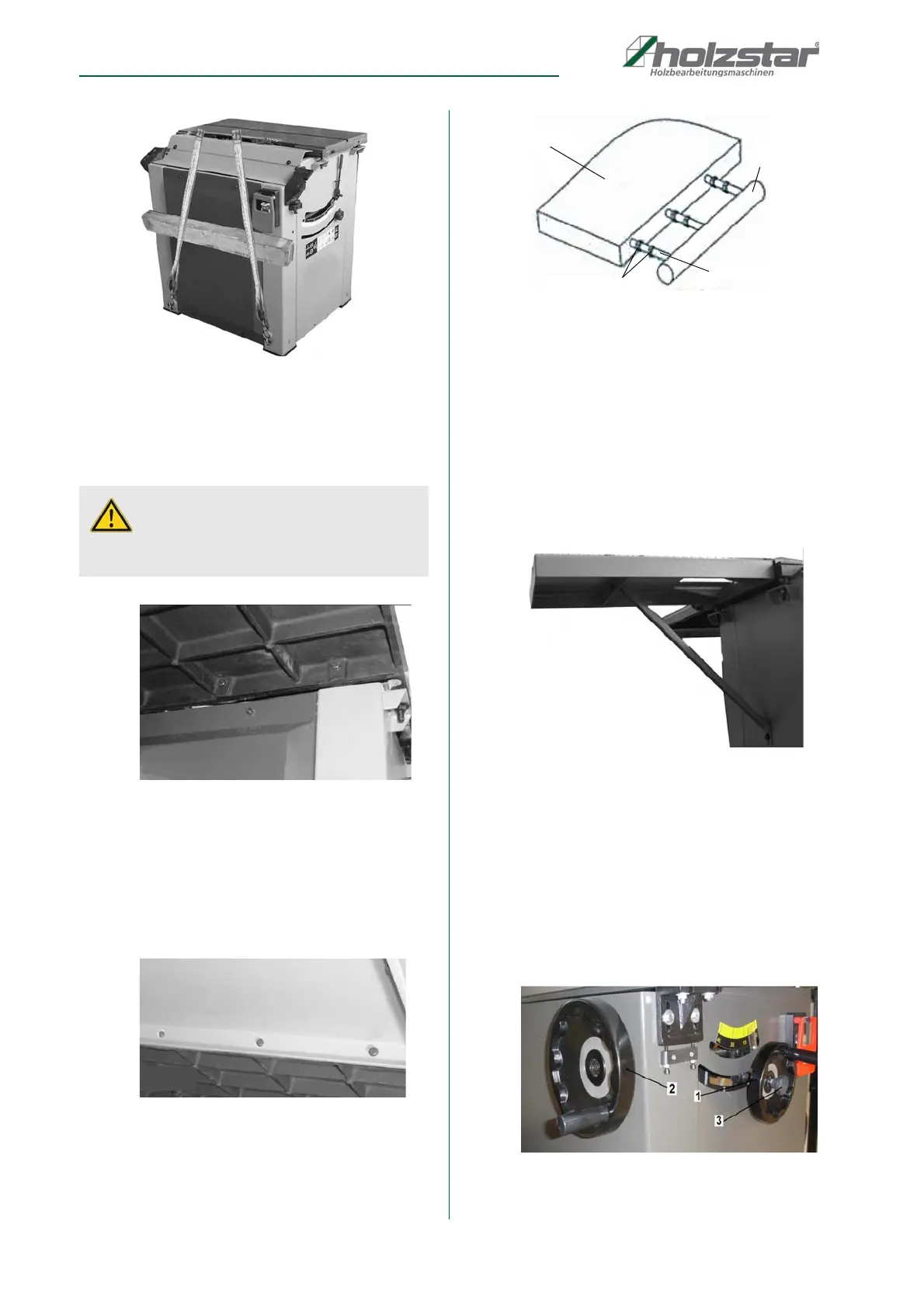
Fig. 9: Preparation for transport
Step 3: Lift the machine and park it at the desired loca-
tion. Before lowering the machine, place four
rubber blocks under the machine frame.
Mount extension tables
Fig. 10: Mount extension table made of cast iron
Step 1: Loosely screw the cast iron extension table (Mo-
del 315-2000 only) with 4 M8x20 hex bolts and
washers on the main table.
Step 2: Check the centering at the corners and the flat
alignment of the surface on the main table with
the help of wooden blocks and spirit level, then
tighten the 4 screws.
Fig. 11: Mount extension table made of steel
Step 3: Loosely screw the steel extension table to the
cast iron table, align and center it, and then tigh-
ten the screws.Anschlag-Führungsschiene mon-
tieren
Fig. 12: Mount the stop guide rail
Step 1: Insert M10x80 hexagon head screws into the
main table and extension tables. Loosely
screw on 2 M10 nuts on each hexagon screw
Step 2: Screw the four screws into the stop guide rail
approx. 4 - 5 turns.
Step 3: Tighten two screws aligning the guide rail paral-
lel. Then tighten the other two screws.
Mount rear extension table
Fig. 13: Screw on the rear extension table
Step 1: Screw the rear extension table to the back of the
main table with 2 M8x16 hex bolts, nuts and
washers. Then screw the support to the table
and the machine housing with M8x16 hexagon
bolts.
Step 2: Position the rear extension table 0.5 mm lower
than the main table.
Mount handwheels, stops and brackets
Fig. 14: Mount handwheels
CAUTION!
The cast iron table is heavy, weighs over 35 kg. To be
on the safe side ensure adequate aids and support.


 To Next Page