Setting up and connection
FKS 315-2000 E | Version 1.11 11
Step 1: Mount the height adjustment handwheel (1) of
the saw blade and the saw blade inclination
handwheel (2) on the corresponding shafts.
Then tighten the locking screw (3) on the hand-
wheel for height adjustment (1).
Fig. 15: Mount swivel arm
Step 2: Screw the swivel arm to the machine housing
with 4 M8x30 hex screws. The swivel arm must
be aligned horizontally.
Step 3: Place the sliding table support (A) on the swivel
arm and hand-tighten the nuts. The carrier still
needs to be set up.
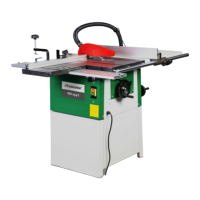
Fig. 16: Mount sliding carriage carrier
Fig. 17: Mount sliding carriage carrier
Step 4: Insert two screws into the lower slots of the sli-
ding carrier and screw the sliding carriage onto
the carrier with two screws.
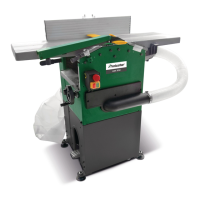
Fig. 18: Mount support leg
Step 5: Screw the support leg onto the sliding carrier.
Step 6: To adjust the level of the sliding carriage, place a
stop on the main table and the sliding table.
Undo the hexagon screws A (Fig.17), adjust the
level of the sliding carriage and tighten the
screws.
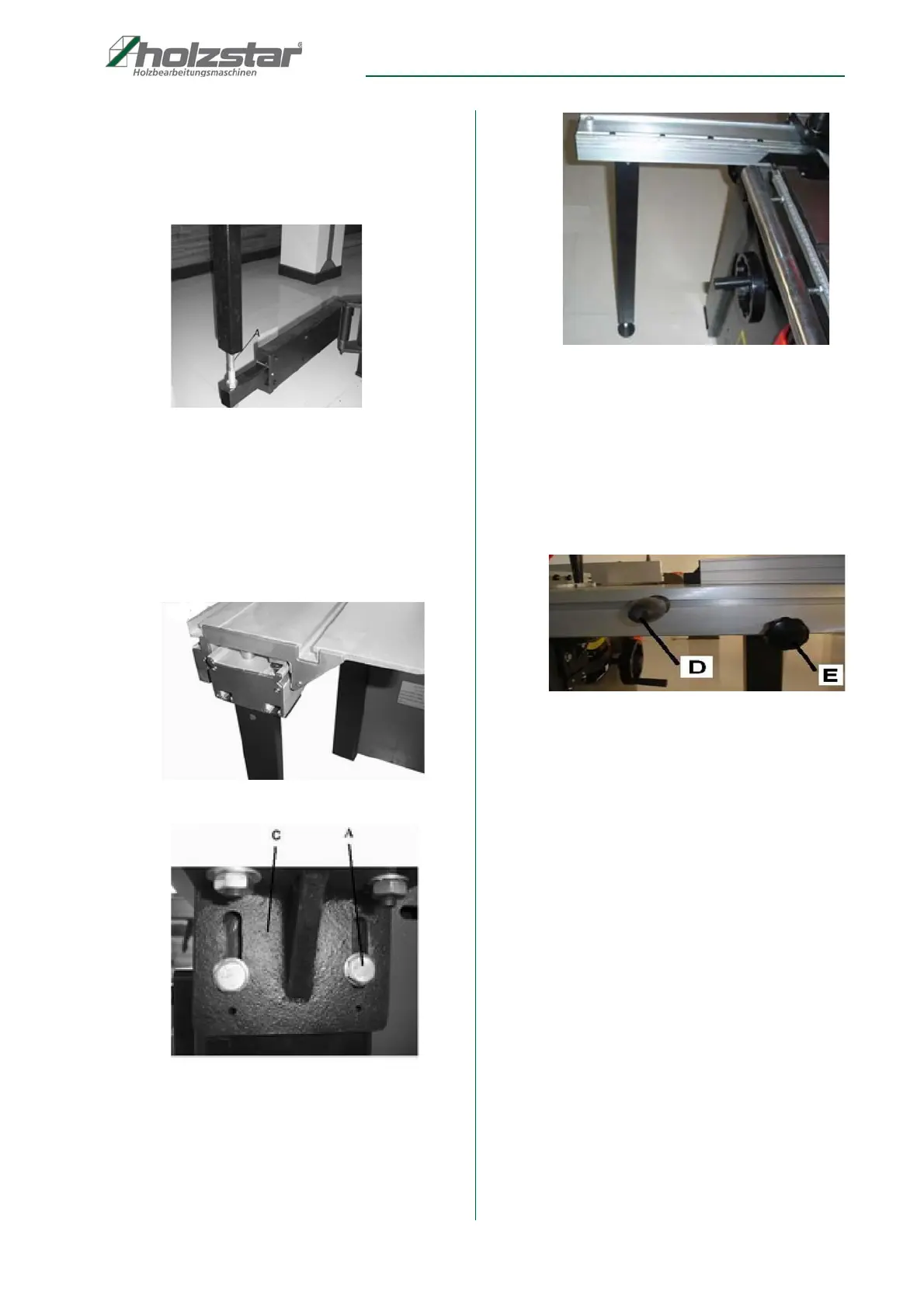
Fig. 19: Mount handle and clamping screw
Step 7: Mount handle D (Fig. 19) on the sliding carriage:
Guide the M12x1.75 T-nut into the groove of the
sliding carriage, place the handle and tighten
with an open-end wrench SW 17.
Step 8: Insert clamping screw E (Fig. 19) into the sliding
carriage and tighten with the M10 nut on the op-
posite side.
Mount sliding table and stops
Step 1: Insert two M8x70 Carriage Bolts into the side
groove of the sliding carriage, place the sliding
table on the sliding carriage and secure with two
wing nuts.
 Loading...