Stack’d Series HOMEGRID Technical
Page 15 Chapter3: How to use Monitoring Software EMS Tools
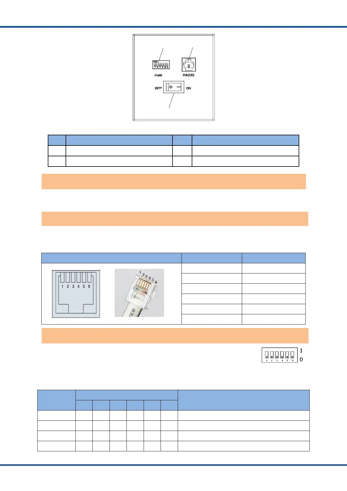
Figure2.4.Batterymoduleinterfacedefinition
No. Instructions NO. Instructions
1 Address Dial Switch 2
RS232communicati on interface
3 Power switch
Power switch: turn on/ off the input and output of the whole battery module.
RS232communicationport: (RJ11 port) comply with RS232 protocol (baud rate: 9600), for
manufacturers or professional engineers debugging or service.
Port definitions RJ11 Pin Function
1 NC (NO CONNECT)
2 RS232-GND
3 RS232-TX
4 RS232-RX
5 RS232-GND
6 NC (NO CONNECT)
ADD Switch: 6 ADD switches,“0”and“1”,refer to the picture at the right.
The setting swill be active only after restart the module.
The top module needs to be “1” or the controller will not turn on.
Address
Coding
Dial Code Switch Position
Definition
#1 #2 #3 #4 #5 #6
1 ON OFF OFF OFF OFF OFF Set to Module 1
2 OFF ON OFF OFF OFF OFF Set to Module 2
3 ON ON OFF OFF OFF OFF Set to Module 3
4 OFF OFF ON OFF OFF OFF Set to Module 4
Address dial switch for modules