Do you have a question about the Honeywell 3400 and is the answer not in the manual?
Details on main power board connections, terminals, communication ports, and I/O board interface.
Information about the display board, its connection, and its role in showing meter readings and errors.
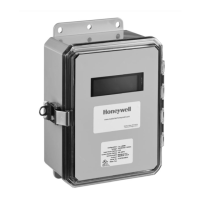
Instructions and dimensions for mounting the meter enclosure to a surface, noting indoor installation requirements.
Step-by-step guide for connecting protective earth ground and the unit's main power wiring to the terminal block.
Detailed steps for installing split-core current sensors around conductors, ensuring correct orientation and clamping.
Instructions for wiring current sensors to the main board, extending wires, and using diagnostic features to verify connections.
Steps for applying power to the meter after wiring and checking the status of the BEAT, STATUS, and LOAD LEDs.
Explains messages like "PH Missing" and "Phase sequence error" indicating line voltage faults.
Details on diagnosing current sensor issues, including reversed sensors, incorrect phase, low power factor, and CT errors.
Guide for connecting meters to a PC via the RS-232 key, including setup of cables and adapters.
Steps for physically connecting the RS-232 key to the computer's serial port and powering it.
Procedures for linking E-Mon meters to the RS-232 key using RS-485 channels for data transfer.
Steps for connecting the RS-485 network to a telephone line using the meter's built-in modem.
Guide for connecting an external modem to the RS-232 key and configuring it for communication.
Instructions for selecting and setting the correct communication baud rate using DIP switches for modem compatibility.
Description of the meter's startup sequence, displaying name, firmware, and configuration information.
How to set load control parameters, including limits, deactivation points, and ramp/hold settings via the display.
Instructions for configuring the meter's internal date and time settings.
Steps to change the meter's Device ID, essential for network identification and communication.
Guide for setting up network IP addresses, subnet masks, and gateway information for Ethernet connectivity.
Procedure to reset the meter's Peak kW Demand to zero through the display menu.
Description of the two pulse inputs for connecting external metering devices with dry-contact outputs.
Details on the two pulse outputs (watt-hours and var-hours) for use with building automation systems.
Information on the expansion board's form "C" relays used for alarming or load control functions.
Addendum focusing on wire entry and ensuring proper grounding for main power board connections.
Addendum providing specific instructions for RS-485 wiring, including the use of a ferrite bead for noise reduction.
| Brand | Honeywell |
|---|---|
| Model | 3400 |
| Category | Measuring Instruments |
| Language | English |