Do you have a question about the Honeywell 5496 and is the answer not in the manual?
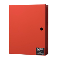
Provides details on the Model 5496 Intelligent Power Module's capabilities and features.
Guides users on determining current requirements for alarm and battery standby operation.
Details the procedure for connecting the 5496 to a 120 VAC power source.
Explains how to connect the 12V batteries in series to provide 24V for the system.
Describes the physical connection of the 5496 module to the Silent Knight addressable FACP.
Guides on using the on-board dipswitch to assign a unique ID number to the 5496 module.
Covers wiring methods for connecting notification appliances to the 5496 outputs.
Explains how to configure output circuits 1-4 as auxiliary power sources.
| Brand | Honeywell |
|---|---|
| Model | 5496 |
| Category | Control Unit |
| Power Supply | 24VDC |
| Operating Voltage | 24VDC |
| Operating Temperature | 32°F to 120°F (0°C to 49°C) |
| Enclosure Material | Plastic |
| Color | Red |
| Humidity Range | 85% RH non-condensing |