151276-L8 Before You Begin Installing
2-3
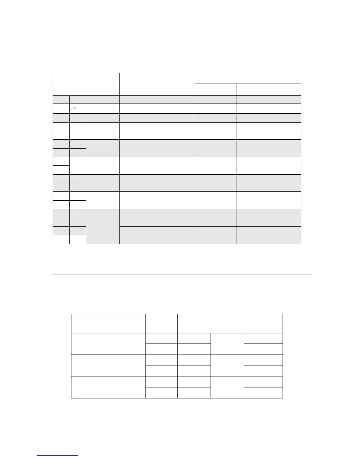
Table 2-1 describes the 5496 connections and provides electrical ratings where
appropriate.
* Regulated/special application when used for releasing.
2.5 Earth Fault Resistance
Table 2-2 lists the earth fault resistance detection for each applicable terminal on the
FACP.
Table 2-1: Terminal Strip Description and Electrical Ratings
Terminal # and Label
Description
Rating
Voltage Current
B AC input (hot) 120 VAC, 60 Hz 2.7 A
Earth ground N/A N/A
W AC input (neutral) 120 VAC, 60 Hz 2.7 A
1 - Battery Battery 24 VDC 0.75 A
2+
3 - I/O 4* Output circuit 24 VDC 3.0 A
Notification Circuits
4 +
5 - I/O 3* Output circuit 24 VDC 3.0 A
Notification Circuits
6+
7 - I/O 2* Output circuit 24 VDC 3.0 A
Notification Circuits
8 +
9 - I/O 1* Output circuit 24 VDC 3.0 A
Notification Circuits
10 +
11 - SBUS SBUS power 24 VDC 1.0 A
12 +
13 A SBUS communication 5 VDC 100 mA
14 B
Table 2-2: Earth Fault Resistance Values by Terminal
Function
Terminal
Number
Terminal Label
Value
(in ohms)
Battery 1 - BATTERY 0
2+ 0
Notification Appliance Circuit
4
3H4-OUT4 0
4H4+ 0
Notification Appliance Circuit
3
5H3-OUT3 0
6H3+ 0

 Loading...