7847i-E Installation and Setup Guide
A-4
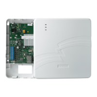
Mode and Status LED Display
The Mode and Status LED Display consists of 4 LEDs. LED 1 (red LED on the left) will be
off, LED 2 and 3 (yellow LEDs) indicate operation mode. LED 4 (1
st
green LED) displays Web
connection status; LEDs 5 and 6 are not used.
Mode and Status Indicator Switch
Press and hold the Mode and Status Indicator Switch to change the LED functions in order
to view the mode of operation and network carrier status. When the switch is held down,
LED 1 (red LED on the left) will be off, and the LEDs from left to right have the following
meanings:
Table 7. LED Functions with Mode and Status Indicator Switch Depressed
LED 1
LED 2
st
LED 3
nd
LED 4
st
OFF
in combination
in combination
Web
Table 7a. Operation Modes
OPERATION
MODE
LED 2
(1
st
yellow)
LED 3
(2
nd
yellow)
Table 7b. Status Indications
STATUS
LED 4
st