EasyManuals Logo
Home>Honeywell>Measuring Instruments>954 SmartServo FlexLine

Honeywell 954 SmartServo FlexLine User Manual

Honeywell 954 SmartServo FlexLine
45 pages
To Next Page IconTo Next Page
To Previous Page IconTo Previous Page
Page #21 background imageLoading...
Page #21 background image
Part No: 4417341 Revision 10 Installation Manual 21
954 SmartServo FlexLine
WARNING!
Use the Hoisting Eye for lifting up the 954 SmartServo FlexLine versions above
18 kg (see picture Appendix A)
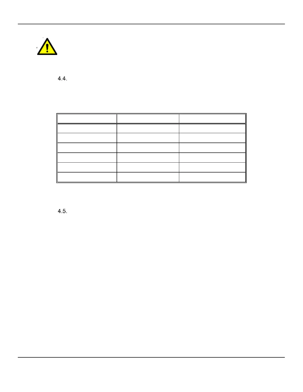
Bolts
Secure the gauge adapter by using appropriate bolts. *)
*) Bolt dimensions (acc. to DIN 2527, ANSI B16.5) are given in the table.
Mounting a Pressure Gauge Set
1. Connect T-piece horizontally to drum house.
2. Check whether manometer is suitable for the maximum pressure in the tank.
3. Mount manometer and vent valve (Figure 6).
4. Close vent valve.
5. Gently open valve between tank and drum compartment and check for leakage
on all connections.
Flange type
Diameter x minimum
length
NW50, ND6
M12 x 50
NW50, ND40
M16 x 60
2", 150 lbs
5
/
8
" x 3" (M16 x 80)
2", 300 lbs
5
/
8
" x 3" (M16 x 80)
6", 150 lbs
3
/
4
" x 3
1
/
4
" (M20 x 80)
6", 300 lbs
3
/
4
" x 4" (M20 x 100)

Questions and Answers:

Question and Answer IconNeed help?

Do you have a question about the Honeywell 954 SmartServo FlexLine and is the answer not in the manual?

Honeywell 954 SmartServo FlexLine Specifications

General IconGeneral
BrandHoneywell
Model954 SmartServo FlexLine
CategoryMeasuring Instruments
LanguageEnglish

Related product manuals