Wiring to Keypads
1. Connect keypads to the control’s keypad terminals as
shown on the Summary of Connections diagram.
Determine wire size using the Wiring Run Chart
below.
If power supervision is required, refer to the Aux
Power Supervision Connections paragraph at
right.
2. Set keypad addresses. Refer to the address setting
instructions included with the keypads and set each
keypad device address according to the chart at right.
3. Program the keypad addresses, partition
assignments and sound options in data fields *190-
*196.
NOTE: Each keypad must be assigned a unique
address, starting at address 16. Keypads
programmed with the same address will give
unpredictable results.
Supplementary Power (optional)
1. Connect as shown. Be sure to connect the negative (–)
terminal on the power supply unit to terminal 4
(AUX –) on the control.
+
–
+
456 7
SUPPLEMENTARY
POWER SUPPLY
–
CONTROL TERMINAL STRIP
AUX.
AUX. DATA
IN
DATA
OUT
IMPORTANT:
MAKE THESE
CONNECTIONS
DIRECTLY TO
SCREW
TERMINALS AS
SHOWN.
TO KEYPAD RED POWER WIRE (V+)
TO KEYPAD BLK GROUND WIRE (V-)
TO KEYPAD YEL DATA WIRE (<)
TO KEYPAD GRN DATA WIRE (>)
TO KEYPAD BLK GROUND WIRE (V-)
TO KEYPAD RED POWER WIRE (V+)
TO KEYPAD GRN DATA WIRE (>)
TO KEYPAD YEL DATA WIRE (<)
pwr_sup_conn-008-V0
Figure 4. Using a Supplementary Power Supply
Notes
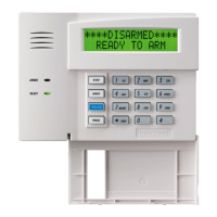
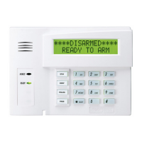
• Typical Fixed-Word Display:
6128RF/6148/6150/6150V
• Typical Alpha Display: 6160/6160V/6164
• The system supports up to 8 keypads, which can
be assigned to partitions in any combination
(see program fields *190-*196).
• For single 4-wire runs, determine the current
drain of all units, then refer to the Wiring Run
chart to determine the maximum length that can
be safely used for each wire size.
• Use supplementary power if the control’s aux.
power load for all devices exceeds 700mA.
Suggested power supply: AD12612
Keypad Addresses
Keypad Address Keypad Address
no. 1 16** no. 5 20
no. 2 17 no. 6 21
no. 3 18 no. 7 22
no. 4 19 no. 8 23
** The first keypad is address 16, which is always
enabled and set for partition 1 with all sounds on.
Aux Power Supervision Connections
To supervise aux power:
1. Use the Trigger Module terminals for ground
and +12V connections (instead of main board
terminals 4 and 5). See Trigger Module and
On-Board Triggers section (page 2-13) for
instructions on mounting the Trigger Module.
2. Connect the SUPV terminal to a zone (+)
terminal.
3. Program that zone as a configurable zone type
programmed as a 24-hour zone and with the
desired report code (CID code 312 is
recommended).
Keypads powered from supplies that do not have a
backup battery will not function if AC mains power
is lost. Make sure to power at least one keypad in
each partition from the control’s auxiliary power
output.
Wiring Run Chart For Devices* Drawing Aux Power From The Control (12V+ & 12V–)
Wire
TOTAL CURRENT DRAIN OF ALL DEVICES CONNECTED TO A SINGLE WIRE RUN
Size 50 mA or less 100 mA 300 mA 500 mA 600 mA
0.6mm O.D. 152m 76m 24m 15m 13m
0.8mm O.D. 228.6m 116m 40m 24m 20m
1mm O.D. 396m 198m 67m 40m 35m
1.2mm O.D. 457m 305m 100m 70m 52m
* Includes Keypads, RF Receivers, Zone Expander/Relay Units, or TeleCommand Phone Module.
Maximum wire lengths for any device that is wired directly to the control can also be determined from the Wiring Run
Chart, based on the current drain of that device alone
.
The length of all wire runs for all partitions combined must not exceed 457m when unshielded quad conductor cable is
used (228m if shielded/screened cable is used). This restriction is due to the capacitive effect on the data lines when
quad cable is used.
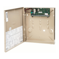
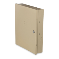
Mounting and Wiring the Control
2-3
 Loading...