Do you have a question about the Honeywell BENDIXKing APEX EDGE Series and is the answer not in the manual?
Grants license for use of materials under specific agreements.
Honeywell retains all rights in materials, including intellectual property.
Materials contain confidential and proprietary Honeywell information.
Agreement may be assigned or transferred to a subsequent owner.
May not make copies without express written permission from Honeywell.
Agreement effective until terminated as set forth herein.
Honeywell reserves right to pursue all remedies for breach.
Honeywell disclaims warranties and limits liability for damages.
Agreement governed by laws of the State of New York.
Clarification for heading SYNC button on 360 deg heading.
Information and contact details for product support.
Accessing Honeywell Online Technical Publications website.
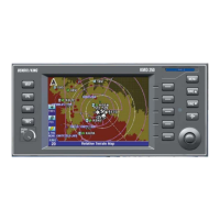
Overview of operating controls and displays of the KFD 840.
Control unit using two rotary knobs and five function keys.
Setting aircraft parameters like Baro Units, Metric Altitude.
Description of the ADI, centered in the top half of the PFD.
Display of blue for sky and brown for ground, separated by a horizon line.
Fixed object in the center of ADI, used with pitch tape.
Identifies current aircraft pitch attitude with numeric labels.
Roll scale on top of ADI with pointer indicating roll attitude.
Indicates lateral acceleration and standard rate turn.
Displayed as a single cue wedge for flight guidance.
Airspeed tape, window, VNE, selected airspeed readout and bug.
Setting and SYNCing the airspeed bug.
Moving scale showing airspeed marks and current indicated airspeed.
White vertical bar showing airspeed prediction in 6 seconds.
Color coding of airspeed tape for various speed limits.
Red bar at VNE and barber pole for over speed warning.
Red bar on lower right of tape for low speed warning.
Selected altitude bug, trend vector, MIN alert, baro setting.
Semi-transparent scale with range -2000 to +34,000 feet.
Displays current barometric altitude with resolution of 20 feet.
Digital metric altitude in meters, requires CONF page setting.
White bar predicting altitude in 6 seconds based on vertical speed.
Red X over tape when altitude data is invalid.
Setting and SYNCing the altitude bug.
Selected altitude readout and magenta bug on tape.
Window below altitude tape for setting barometric pressure.
Setting and SYNCing the minimum altitude alert.
Yellow box indicates MIN condition is armed.
Indicates ILS glide slope or GPS glide path deviation.
Red X over scale when vertical deviation data is invalid.
Shows rate of altitude changes in feet per minute (fpm).
Fixed scale and moving pointer indicating altitude rate +/- 3000 fpm.
Indicates rate of climb or descent, range -9999 to +9999 fpm.
Red X replaces scale and pointer when data is invalid.
HSI window in lower portion of PFD, describes displays and annunciators.
360-degree heading display that moves clockwise/counterclockwise.
Digital representation of compass heading, three digits.
Heading select bug moves with HDG knob rotation.
Magenta off-scale arrow points to selected heading bug.
Red HDG FAIL flag displayed when heading data is invalid.
Digital readout and cyan pointer for selected course.
Four-dot scale shows lateral deviation from selected course.
Two green pointers indicating VOR or GPS NAV source.
Select source (O BRG / ◊ BRG) with soft keys.
Waypoint identifier and distance displayed near upper right corner.
Select navigation source (VLOC, GPS) using CDI button.
Colored triangle indicating direction to/from NAV source or waypoint.
Accessing and displaying checklist pages via MENU and CHK LST buttons.
Displays checklists on upper right corner when CHK ON is selected.
Shows a sample checklist display with items and page numbers.
Procedure to enter maintenance mode for checklist loading.
Procedure to save selected checklist to the KFD 840.
Labels for wind, speed, and temperature are on the left side of HSI.
Digital readout for wind speed and direction from GPS1.
Displayed in lower left of PFD in knots/miles per hour.
Calculated based on indicated airspeed, displayed in kt/mph.
Displayed in degrees Celsius or Fahrenheit.
Red X's over airspeed, altitude, VS for ADC failure.
ATTITUDE FAILURE message in red for AHRS failure.
HDG FAIL message for CRM failure, removes heading data.
System capable of partial reset in-flight under emergency conditions.
Messages related to configuration module mismatches or failures.
Amber dashes for non-critical or secondary parameter failures.
Definitions of terms and abbreviations used in the guide.
Reference for KFD 840 configuration parameters installed in the aircraft.
| Display Type | LCD |
|---|---|
| Operating Temperature | -20°C to +55°C |
| Power Supply | 28 VDC |
| Certifications | DO-160 |
| Input Voltage | 18-32 VDC |