CLIF-CBUSLC INTERFACE – INSTALLATION & COMMISSIONING INSTRUCTIONS
EN1Z-1026GE51 R0417 10
lower, the automatic installation does not work: Please down-
load the appropriate USB driver prior to the installation at:
http://catalog.update.microsoft.com/v7/site/ScopedViewRedire
ct.aspx?updateid=37e35bd4-d788-4b83-9416-f78e439f90a2
Please connect the controller to the PC as described in
section "Windows 8" and perform the general installation
procedures for drivers in Windows 10.
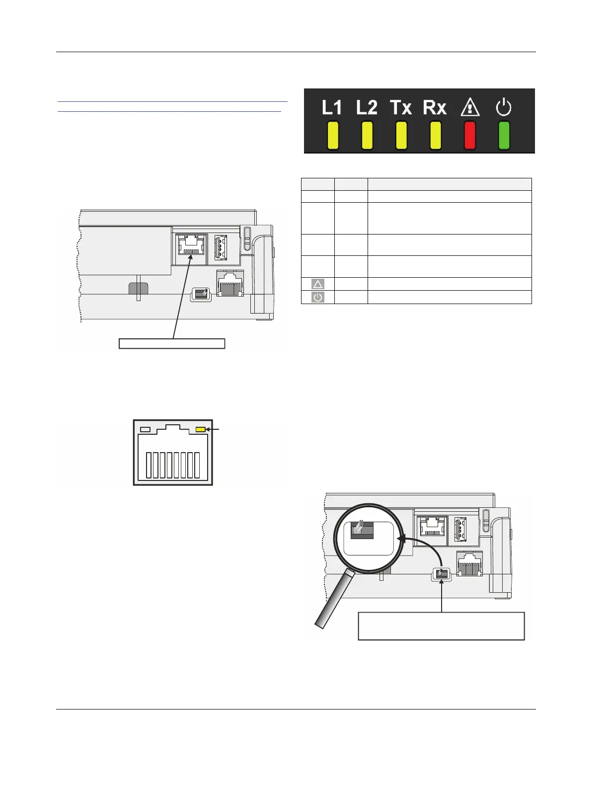
Ethernet / RJ45 Socket
The CLIF-CBUSLC is equipped with an Ethernet / RJ45
socket featuring one LED.
J1 J8
Ethernet / RJ45 socket
Fig. 7. Ethernet / RJ45 socket
This Ethernet / RJ45 socket is a 10/100-Mbaud Ethernet
interface permitting communication with a SUSI client like
ARENA
AX
, ARENA
NX
, COACH
AX
, COACH
NX
, or ARENA 3.0
(as per IEEEC 802.3)
LINK/ACT.
Fig. 8. Ethernet / RJ45 socket
NOTE: The Ethernet / RJ45 socket is usually earth-
grounded. For additional information on earth
grounding, see also "Appendix 1: Earth Grounding"
on pg. 22.
LEDs
The CLIF-CBUSLC features the following LEDs:
Fig. 9. CLIF-CBUSLC LEDs
Table 5. CLIF-CBUSLC LEDs
symbol
color function, description
L1 yellow unused
L2 yellow
LED indicating that a SUSI client
(ARENA
AX
, COACH
AX
or ARENA 3.0) is
connected
Tx yellow
RS485-1 status LED indicating trans-
mission of C-Bus signals
Rx yellow
RS485-1 status LED indicating reception
of C-Bus signals.
!
red status LED indicating hardware problems
green power LED
See also section "Troubleshooting" on page 21 for a detailed
description of the behaviors of the LEDs and their meanings.
RS485 Interface
General
The CLIF-CBUSLC has one C-Bus interface:
RS485-1 (consisting of push-in terminals 24 [GND-1], 25,
and 26) is isolated.
RS485-1 Bias and Termination Resistors
RS485-1 is equipped with a three-position slide switch which
can be used to switch its bias resistors OFF (position "MID" –
this is the default and the only allowed setting), ON (position
"BIAS"), and ON with an additional 150Ω termination resistor
(position "END").
J1 J8
RS485-1
3-POSITION SLIDE SWITCH
MID
BIAS
END
Fig. 10. RS485-1 three-position slide switch
The slide switch setting must remain in the leftmost position
for "MID".

 Loading...