Installation
1. Position the side scan PCB at its location on the scan bracket assembly.
2. Using a #0 Phillips screwdriver install 2 screws and secure the side scan PCB to the scan bracket assembly with
1.2+/-0.2 in-lbs of torque.
3. Re-install the bottom housing assembly.
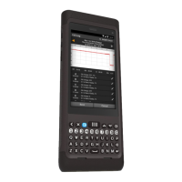
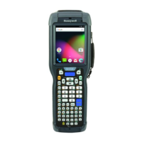
There are two styles of keyboard/keypad assemblies that have been produced. Original production used a conductive trace
and puck keyboard/keypad combination (shown at left in picture below). Current production uses a snap dome switch and
plunger keyboard/keypad combination (shown at right in picture below).
Do not mix assemblies. A conductive trace keyboard PCBA should always be used with a conductive puck keypad. A
snap dome keyboard PCBA should always be used with a plunger style keypad. Units should be repaired with the style of
keyboard/keypad they were originally built with.
Conductive trace style snap dome switch style
Tools Required
 Loading...