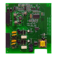
DACT-E3 Product Installation Document — P/N 9000-0581:J6 12/16/2019 5
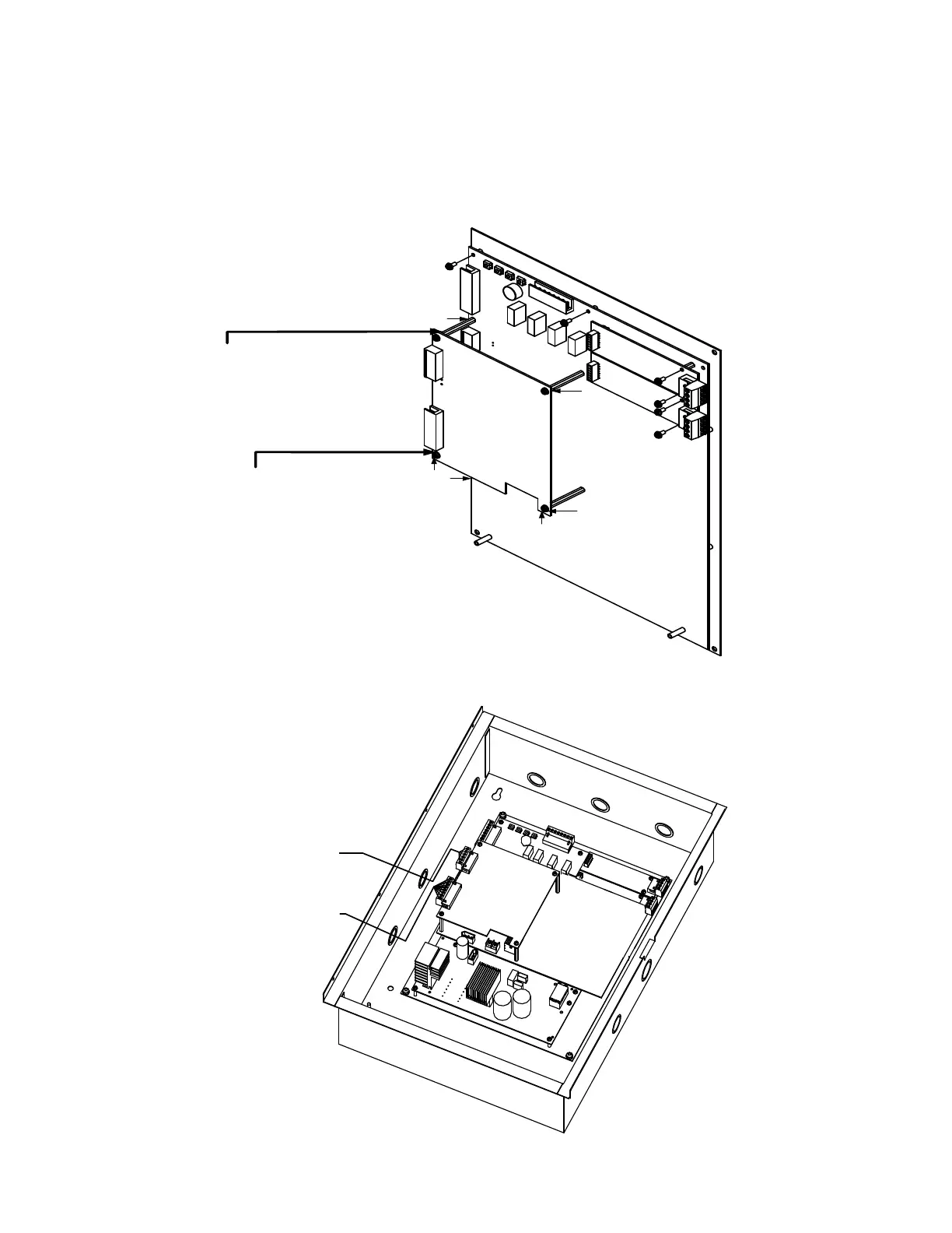
2.3.1.2 DACT-E3 Installation in an S3 Series, Cabinet Configuration
In an S3 Series, SLP-BB cabinet configuration, the PCB orientation of the DACT-E3 sub-assembly is usually installed above the
SLP-E3 sub-assembly as part of a backbox configuration. To install the DACT-E3, refer to the following instructions.
1. Insert and secure four standoffs (3/16” HEX #4-40, x 1 1/) to the SLP-E3 as shown in Location 1 of Figure 2.3.1.2.1.
2. Align and place the DACT-E3 on top of the SLP-E3.
3. To mount the DACT-E3 to the SLP-E3, insert and secure four screws (#4-40 x 1/4”) into the four standoffs as shown in
Location 2 of Figure 2.3.1.2.1.
Figure 2.3.1.2.1 DACT-E3 to S3 Mounting Plate Installation
Figure 2.3.1.2.2 illustrates the DACT-E3 installed in the SLP-BB cabinet.
Figure 2.3.1.2.2 DACT-E3 Installed in the SLP-BB Cabinet
S
L
C
-
P
M
/
S
L
C
9
5
-
P
M
S
L
C
-
P
M
/
S
L
C
9
5
-
P
M
D
A
C
T
-
E
3
S
L
P
-
E
3
STANDOFF, M/F,
(#4-40 x 1-½” (38.10 mm))LG
(4 PLACES)
SCREW,
(#4-40 x ¼” (6.35 mm))
LG, PHPD SEMS
(4 PLACES) DACT TO
STANDOFF MOUNTING
S
3
M
O
U
N
T
I
N
G
P
L
A
T
E
1
2
1
1
2
2
2
1
D
A
C
T
-
E
3
S
L
P
-
E
3
AUXILIARY RS485
FROM DACT-E3 TB2
(CLASS 2
POWER-LIMITED)
TELEPHONE LINES
FROM DACT-E3 TB2
(CLASS 2
NON POWER-LIMITED)
T
B
1
T
B
2
T
B
1
T
B
1
F
L
P
S
-
7
S
L
C
-P
M
#
2
S
L
C
-
P
M
#
1