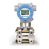
Do you have a question about the Honeywell SMV 3000 and is the answer not in the manual?
Explains the SCT 3000's features for configuring, calibrating, and diagnosing smart field devices.
Details how to mount the SMV 3000 transmitter using brackets on pipes and considerations for orientation.
Explains piping arrangements, transmitter location for gas/liquid flow, and flange adapter installation.
Details wiring procedures for signal/power, RTD, thermocouple, and lightning protection.
Explains off-line vs. on-line configuration and details SCT hardware connections for on-line communication.
Details using SCT template files with tab cards to configure SMV parameters like PV1, PV2, PV3, and PV4.
Details configuring PV1 (Differential Pressure), including engineering units, LRV/URV, and output conformity.
Covers configuring PV2 (Static Pressure), including engineering units, LRV/URV, and atmospheric offset.
Explains configuring PV3 (Process Temperature), including engineering units, cold junction compensation, and sensor type.
Details configuring PV4 (Flow), including volumetric/mass units, LRV/URV, damping, and low flow cutoff.
Describes the wizard for configuring PV4 output with standard or dynamic compensation flow equations.
Details procedures for checking analog output signals and PV outputs in DE mode.
Explains how to use the input mode to simulate PV inputs for checking transmitter output and loop readings.
Provides startup procedures for various SMV 3000 models and typical connections for the procedure.
Provides step-by-step procedures for replacing the electronics module or the plug-in PROM.
Explains how to replace the meter body center section, including installing a new matching PROM.
Details how to calibrate the transmitter's analog output circuit at 0 and 100% levels using SCT or SFC.
Explains the two-point calibration process for PV1 and PV2 ranges (LRV and URV) using SCT or SFC.
Lists diagnostic text messages displayed on SCT, SFC, or TPS/TDC systems with probable causes and actions.
Details the Dynamic Compensation Flow Equation for accurate PV4 measurement of liquids, gases, and steam.
| Manufacturer | Honeywell |
|---|---|
| Product Type | Smart Multivariable Transmitter |
| Measurement Parameters | Differential Pressure, Static Pressure, Temperature |
| Accuracy (Differential Pressure) | ±0.04% of span |
| Accuracy (Static Pressure) | ±0.1% of Span |
| Operating Temperature | -40 to 85°C |
| Communication Protocol | HART |
| Output | 4-20 mA HART |
| Power Supply | 10.5-42 V DC |
| Process Connection | 1/4" NPT |
| Materials | 316L Stainless Steel |
| Protection Rating | IP66/67 |


