1/99 SMV 3000 Transmitter User’s Manual 73
6.9 FlowConf Configuration - PV4, Continued
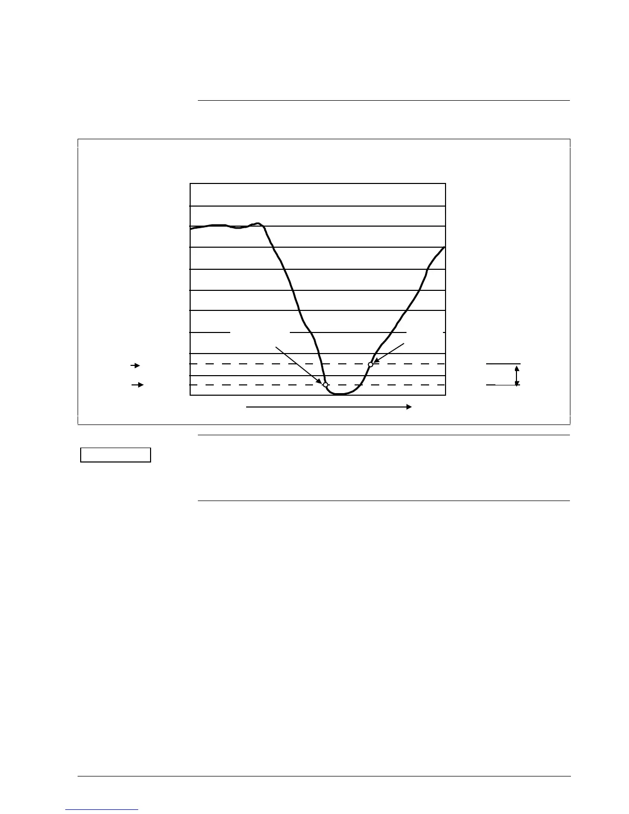
Figure 25 Graphic Representation of Sample Low Flow Cutoff Action.
1100
990
880
770
660
550
440
330
220
110
0
100
90
80
70
60
50
40
30
20
10
0
Time
100
90
80
70
60
50
40
30
20
10
0
Low Limit
High Limit 165
55
15
5
15
5
PV4 Range
GPM %
Output
%
20.0
18.4
16.8
15.2
13.6
12.0
10.4
8.8
7.2
5.6
4.0
6.4
4.8
mA
During
Cutoff
0/
4.0*
Flow Rate
Flow Rate
enters cutoff*
Flow rate
leaves
cutoff*
* During cutoff,
output equals 0%
ATTENTION
The low flow cutoff action also applies for reverse flow in the negative
direction. For the sample shown in Figure 25, this would result in a low
limit of –55 GPM and a high limit of –165 GPM.
Continued on next page
 Loading...


