Configuration
8/05 DC1010/1020/1030/1040 Product Manual 29
4.3 ALARMS CONFIGURATION
4.3.1 Alarm Function Selections
These Alarm Function Selections are entered in “Configuration 2”. See Section 4.2.1.
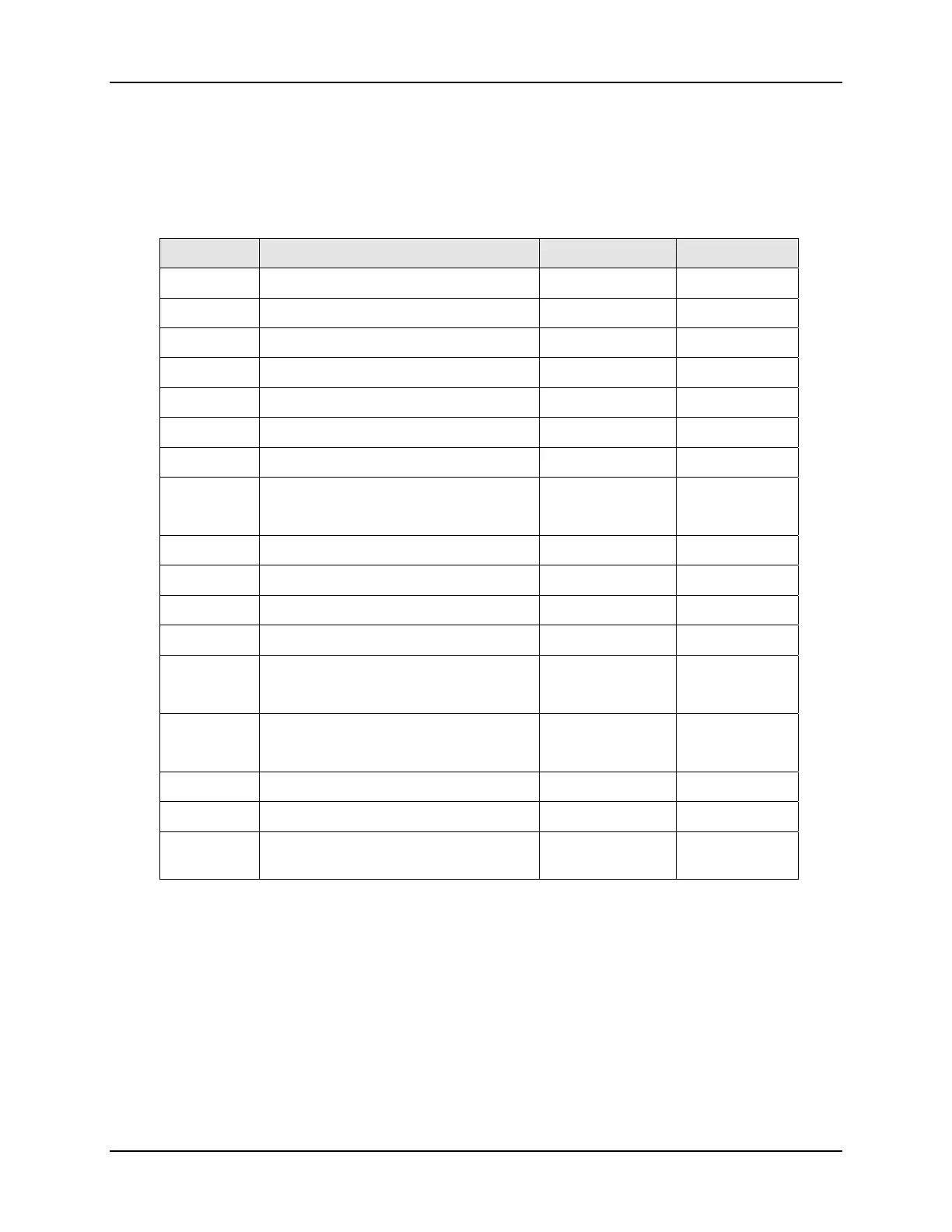
Table 4-3 Alarm Function Selections
Code Description Hold-ON Refer to
00 / 10
None
01
Deviation high alarm YES Figure 4-2
11
Deviation high alarm NO Figure 4-3
02
Deviation low alarm YES Figure 4-4
12
Deviation low alarm NO Figure 4-5
03
Deviation high / low alarm YES Figure 4-6
13
Deviation high / low alarm NO Figure 4-7
04 / 14
Band alarm NO Figure 4-8
Figure 4-9
05
Absolute value high alarm YES Figure 4-11
15
Absolute value high alarm NO Figure 4-12
06
Absolute value low alarm YES Figure 4-13
16
Absolute value low alarm NO Figure 4-14
07
Segment end alarm
(Use for program model only)
- Paragraph
4.3.4.1
17
Program run alarm
(Use for program model only)
- Figure 4-15
08
System error alarm (On) - Figure 4-16
18
System error alarm (Off) - Figure 4-17
19
Soak timer - Paragraph
4.3.5.3
“Hold-On”(Blocking) means that the alarm does not work at the first time. The alarm
signal is suppressed until the parameter gets to the non-alarm limit or band.

 Loading...


