Enhanced Micro TDC 3000 User’s Manual 5-18 9/95
5.4.1
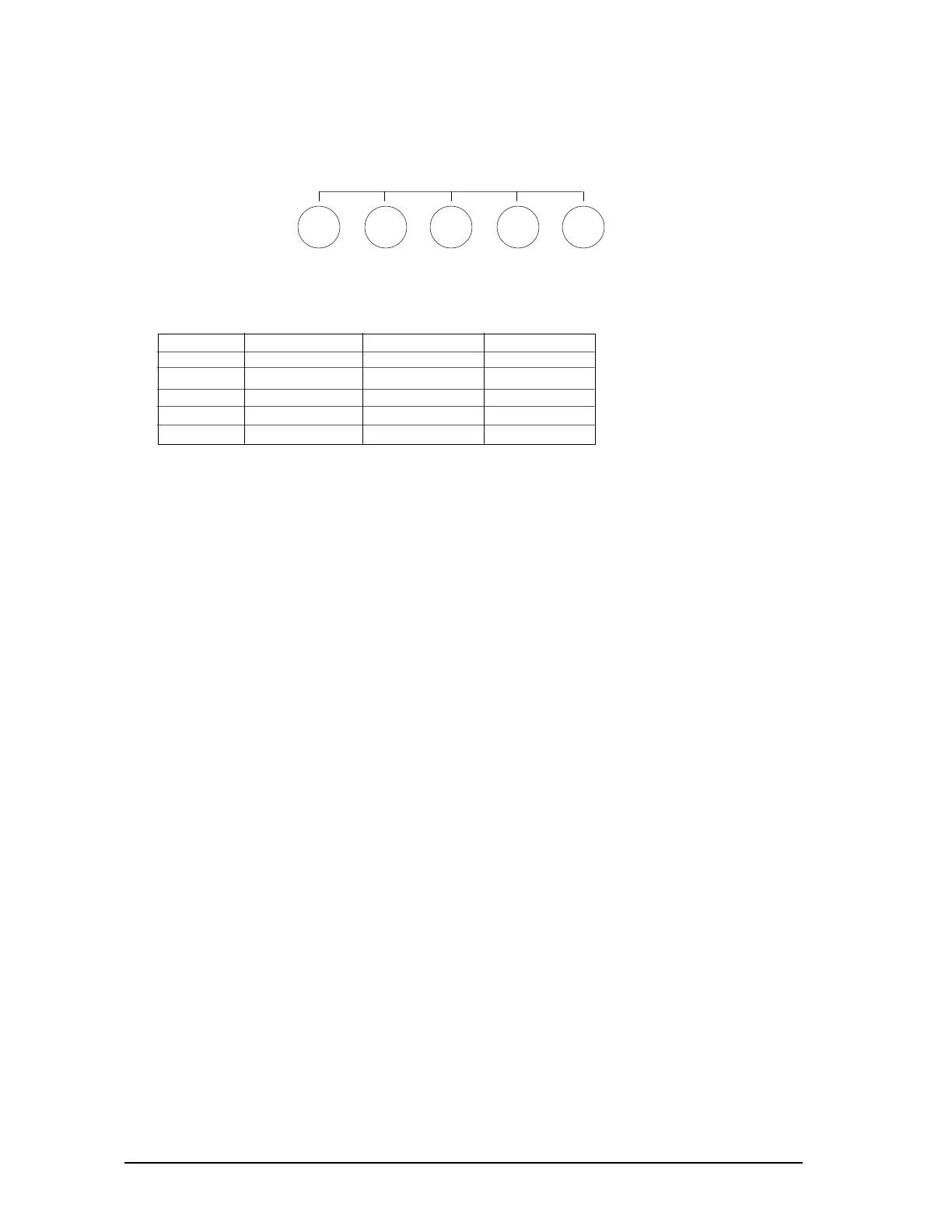
15. ANALOG RGB INPUT connectors (5 BNC)
Allows a computer having analog RBG output to be connected.
R G-SYNC B H/H
V
11042
BNC analog signals
Connector
R
G/SYNC
B
H/HV
V
Sync on Green
Red
Sync on Green
Blue
GND/unused
GND/unused
Composite sync
Red
Green
Blue
HV sync
GND /unused
Separate sync
Red
Green
Blue
H-sync
V-sync
16. TERMINATION switches
Select the appropriate line impedance (75Ω or infinity) for video and
(1 KΩ or 4.7 KΩ) for sync.
If the monitor is used in a loop-through operation, set these switches to the left
(infinity for video, 4.7 K for sync). For single unit operation, or when the monitor is
the last unit in a loop-through string, set these switches to the right (75 for video, 1 K
for sync). The switches of unused BNC connectors should also be set to the right.
 Loading...


