Enhanced Micro TDC 3000 User’s Manual 2-13 9/95
2.7.4
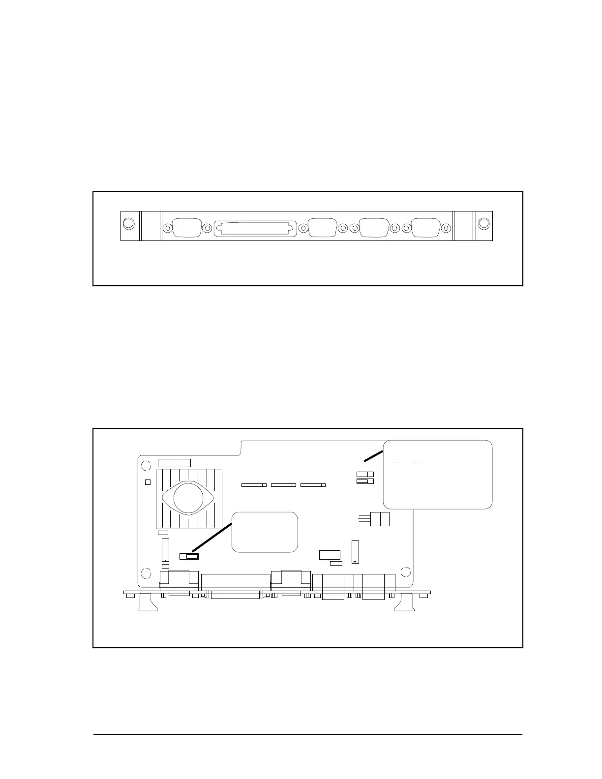
2.7.4 Cabling EPDGC I/O Board
The EPDGC I/O is the EMC Directive board version used to interface with the monitor,
keyboard, touchscreen, SCSI cartridge drives and printers. The EMC Directive version is
shown in Figures 2-12 and 2-13. All the connectors have been converted to D-type
connectors with full 360 degree shielding. The connectors are bulkhead mounted into the
board face plate which provides a contiguous shield from module to cable. The cabling of
peripheral devices are connected at this face plate. The Touchscreen and Trackball cables
are connected to the cabinet bulkhead shown in Figure 2-7.
53369
VIDEO SCSI CURSOR PRINTER KEYBD
Figure 2-12 — EPDGC I/O Face Plate
The background color of the monitor can be selected as one of four colors as shown in
Figure 2-13. The pinning shown is for the default background color. Pin the board for
desired background color. The pinned background color selection is only in force until the
station is loaded with software.
The sync pulse requirements of the monitor used is pinned at J6 (factory set) as shown in
Figure 2-13. The pinning of J6 will determine the tab number of the board and is factory
set. The monitor sync pulse source will either be direct (Tab 100) or inverted (Tab 200).
53389
ASSY NO. 51402447-100 REV A
BAR CODE
EPDGC I/O
J7
J8
0 1
0 1
Default CRT Background
J7 J8
1 1 Black
1 0 Dark Grey
0 1 Med. Grey
0 0 Light Grey
J1
J2
J3
J4 J5
J6
Tab 100 - "DIR"
Tab 200 - "INV"
Factory Set
Figure 2-13 — EPDGC I/O Pinning
 Loading...


