Enhanced Micro TDC 3000 User’s Manual 2-12 9/95
2.7.3
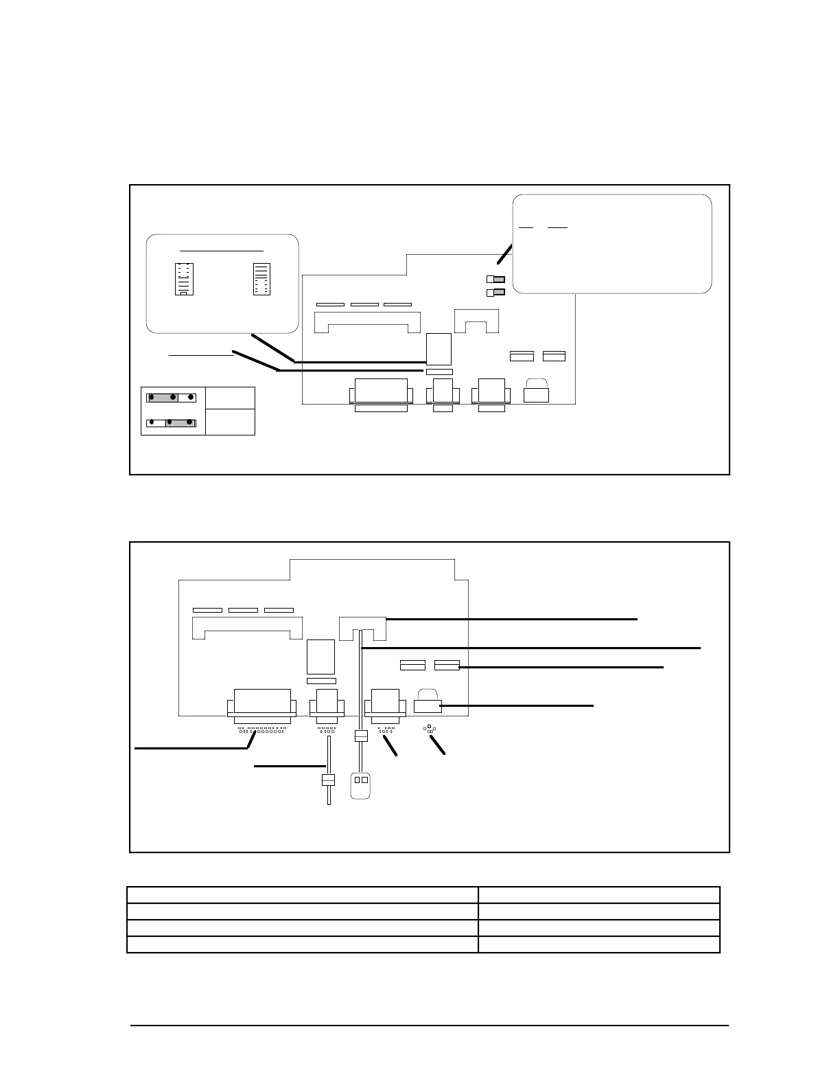
2.7.3 Cabling EPDGP I/O Board
EPDGP I/O boards (see Figures 2-10 and 2-11) interface nearly all the peripherals of the
Enhanced Micro TDC 3000 Control System. You are now going to connect those cables
which could not be installed at the factory.
51090
51304584-300
EPDGP I/O
J5 J4
J2 J7 J3 J6
J1
TS1
TSI Orientation
J10
J9
0 1
0 1
J11
J11 Pinnin
J8
Default CRT Background
J9 J10
1 1 Black
0 1 Light Grey (Dim)
1 0 Med. Grey (Brighter)
0 0 Warm Grey (Brightest)
Engineer
Keyboard
Supervisor
Keyboard
DIR VSYNC INV
DIRECT
INVERT
Jumper Vertical Sync
Signal
Figure 2-10 — CRT Background Shade Pinning and Sync on the EPDGP I/O
EPDGP I/O boards can be pinned for default background shading(J9 and J10) and vertical
sync (J11) for the monitor as shown in Figure 2-10.
51091
51304584-300
EPDGP I/O
J5 J4
J2 J7 J6
J1
TS1
J11
J8
Mouse Adapter Cable #51304033-045
Engineer Keyboard
SCSI
Trackball/Mouse Connector
CRT Adapter Cable
Printer Connector
Mouse or Trackball
Engineer
Keyboard
Superviso
Keyboard
Cable from CRT
Power (Touchscreen/Keyboard)
J3
Figure 2-11 — EPDGP-I/O Cabling
Universal Station Type EPDGP I/O Assembly
Classic with keyboard power supply 51304584-100
Classic without keyboard power supply 51304584-200
Ergonomic furniture with 21” FST monitor 51304584-300
 Loading...


