Enhanced Micro TDC 3000 User’s Manual 2-10 9/95
2.7.2
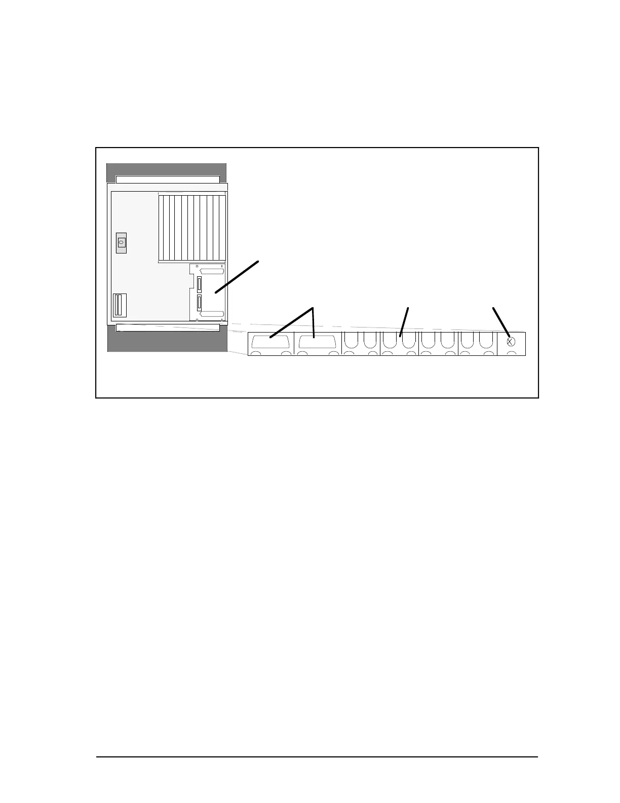
3. For EMC Directive cabling, the connections you will make in the following steps is on
the transition panel shown in Figure 2-7. Note there is one exposed transition panel
located at the bottom (see Figure 2-7). The panel has connectors and cable clamps on it
that will be used to secure cables you will install. Both towers have the same locations
for specific connector/clamp brackets but the bracket types in certain locations may
differ depending on the options installed.
53899
Optional PLCG
Relay Panel
UCN Taps
Ground (Option)
Options:
PLCG, CG, NG
Touchscreen (Option)
or
Trackball (Option)
Figure 2-7 — Transition Panel Connections for EMC Directive—Rear View
4. Note the Optional EPLCG Relay Panel in Figure 2-5 above. It can be mounted above
the transition panel, as shown, in the tower containing an optional EPLCG (see Section
2.8.5).
Figure 2-8 and Figure 2-9 shows the EMC Directive TP-485-3 I/O board face plate. The
designed cable(s) attached to this card face plate is also terminated to ground (sheet metal
module) through the attaching screw on the face plate. This I/O board provides the current
loop interface between the modules located in an Enhanced Micro TDC 3000 tower.
 Loading...


