Fire Alarm Control Panel IQ8Control C / M
58 FB 798951.10.GB0 / 04.15
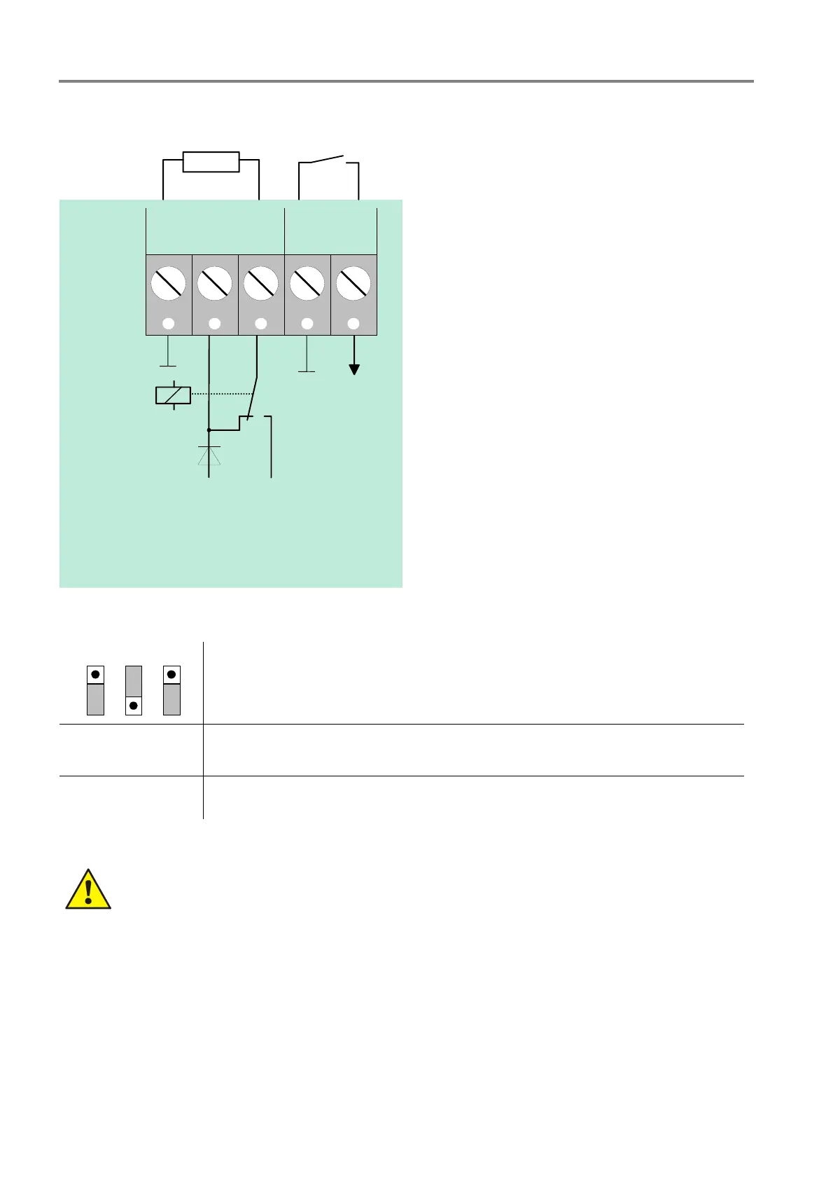
Operating mode 1 Relay K1 positive switching and monitored
680
R *
S*
CNCNO
BACK
GND
K1
+12V DC Ub int.
K1
+monitoring
Panel internal
V
*
Fig. 49: Terminal of the master box relay K1
BR8 BR7 BR6
1
2
3
1
2
3
1
2
3
Relay K1
positive switching (+12 V DC
intern
/ max. 1 A) and monitored
R*
Monitored end-of-line resistor R = 680 (factory setting) Monitoring capability of
internal resistor in master box 50 to 1000
(refer to customer data programming)
S*
Dry confirmation contact in master box
Diode V*
From Hardware index B the diode V* is integrated in the Field device module.
Observe permitted torque (max. 0.4 Nm) of the terminals!

 Loading...


