Fire Alarm Control Panel IQ8Control C / M
62 FB 798951.10.GB0 / 04.15
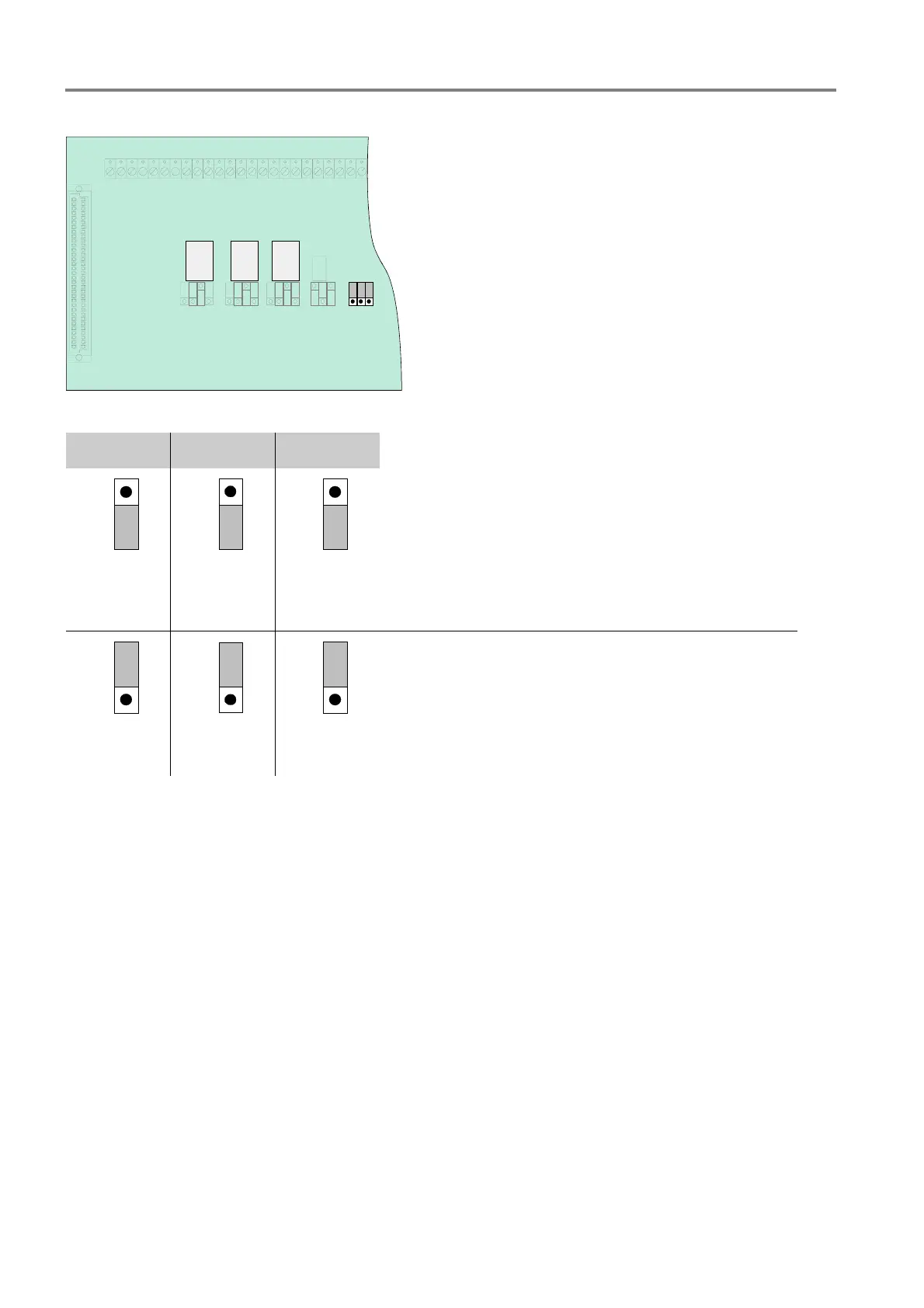
CPU failure mode function of relays K2, K3 and K4
1
2
3
BR 5
BR 4
BR 3
K3K4 K2
Fig. 54: Location of the emergency mode jumpers BR3 to 5 on the Field device module
K2 K3 K4
BR 4
1
2
3
BR 3
1
2
3
BR 5
1
2
3
Jumper X in position 1/2
No activation of the relay while the Fire Alarm Control
Panel is in CPU failure mode (state on leaving factory).
BR 4
1
2
3
BR 3
1
2
3
BR 5
1
2
3
Jumper X in position 2/3
Relay also activated while the Fire Alarm Control Panel is
in CPU failure mode.
Used if a common function is programmed for the relays,
such as >common fire<, >common alarm< and >common
disconnection<.

 Loading...


