24
FS20X Fire and Flame Detectors
Detector Connections
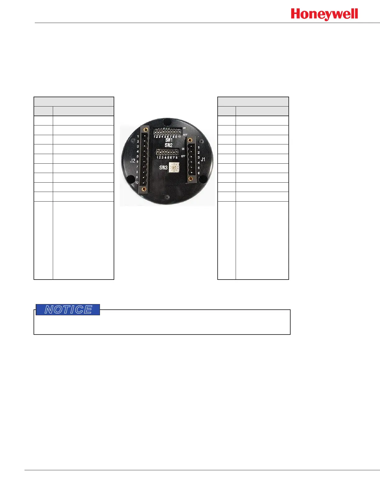
The electronics module has six-pin and ten-pin keyed, removable connectors with
female screw terminal plugs. These connect to the two respective male connectors
with analog, digital, and relay interfaces (see Figure 16). Use the ten-pin plug (J2)
and connector for relay configurations. For digital and analog configurations, use the
six-pin plug (J1) and connector.
J2 Connector J1 Connector
Pin Connection Pin Connection
1 Auxiliary NC 1 DC return
2 Auxiliary NO 2 RS-485-A
3 Auxiliary COM 3 RS-485-B
4 Alarm NC 4 +24 VDC
5 Alarm NO 5 4-20mA source
6 Alarm COM 6 4-20mA sink
7 Fault NO
8 Fault COM
9 +24 VDC
10 DC return
Figure 16. Electronics module, rear view (contacts shown with no power applied)
Do not open the electronics module as this will void all warranties.
Avoid wire splices whenever possible. Good wiring practices simplify installation,
improve reliability, and facilitate maintenance. If wire splices are necessary, solder
and properly insulate them.

 Loading...


