16
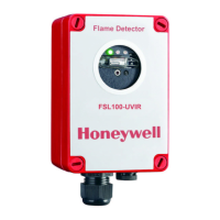
FS20X Fire and Flame Detectors
Installation
Installation Practices
For installations in a Hazardous Classified Area, consult the National Electrical
Code Handbook, articles 500 through 517 for the proper installation practices. For
locations outside the United States, observe local and regional regulations.
The detector’s metal conduit plug by itself will not provide a weathertight seal.
To maintain the detector’s weatherproof integrity and satisfy local and regional
regulations, apply an approved sealant to the threads.
Before completing the installation, verify that the detector has been configured
correctly for the application. The factory default settings are as follow:
FS20X Settings for SW VER I/F 6175009G and earlier
Description Setting
Alarm relay outputs are non-latching and normally de-energized SW2-1 off SW2-7 off
Detector range/sensitivity is medium SW2-2 off SW2-3 on
Auxiliary relay Verify Time is set to 5 seconds SW2-4 on SW2-5 off
Factory use only SW2-6 off
Fault relay output is normally energized SW2-8 on
Communication is set to FireBusII SW3 is set to position 4
Factory use only SW1-1 through SW1-3 off
Digital communication address is set to 127 SW1-4 through SW1-10 on
FS20X Settings for SW VER I/F 6175009H and later
Description Setting
Alarm relay outputs are non-latching and normally de-energized SW2-1 off SW2-7 off
Detector range/sensitivity is medium SW2-2 off SW2-3 on
Auxiliary relay Verify Time is set to 5 seconds SW2-4 on SW2-5 off
Factory use only SW2-6 off
Fault relay output is normally energized SW2-8 on
Communication is set to FireBusII SW3 is set to position 4
Factory use only SW1-1 & SW1-3 off
8, 12 and 16 mA controls (see table below for details) SW1-2
Digital communication address is set to 127 SW1-4 through SW1-10 on
If the detector’s application requires different settings, refer to “Configuring the
Detector” on page 31 for detailed descriptions.
 Loading...


