38
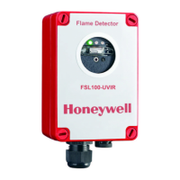
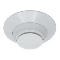
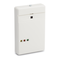
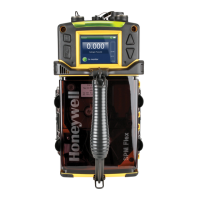
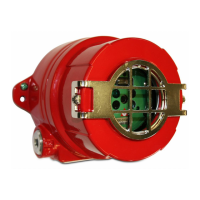
FS20X Fire and Flame Detectors
Specifications
Mechanical
Description Value
Enclosure Materials
copper-free aluminum (red)
316 stainless steel
Dimensions
Assembly 4.35 in. (110.49 mm) H × 4.81 in. (122.24 mm) Dia
Mounting holes ¼ in. (6.35 mm) Dia, 5½ in. (139.70 mm) center-to-center
Conduit entries Two ¾ in. NPT or two 25 mm
Weight
Aluminum 3 lbs. 11 oz. (1.7 kg) approximately
Stainless steel 7 lbs. 7 oz. (3.4 kg) approximately
Enclosure Rating IP66, NEMA 4, NEMA 4X
Vibration meets or exceeds Mil Spec 810C, Method 514.2, Curve AW
Electrical
Description Value
Input voltage range 18 VDC to 32 VDC
Normal operation current 85 mA (nominal), 175 mA (nominal with heater
1
)
Maximum fire alarm current 135 mA (maximum), 220 mA (maximum with heater
1
)
Relay contact rating 1 Amp @ 24 VDC resistive
Analog current output
2, 3
0.0 to 20.0 mA (Non-isolated source or sink, user selectable)
0.0 mA (<0.6 mA) = Fault
2.0 mA (±0.6 mA) = Dirty window
4.0 mA (±0.6 mA) = Normal, safe (no fault, no fire)
8.0 mA (±0.6 mA) = Background IR
12.0 mA (±0.6 mA) = Background UV
16.0 mA (±0.6 mA) = Fire alarm
20.0 mA (±0.6 mA) = Verified fire alarm
Screw terminal wire sizes 12 AWG to 22 AWG (2.50 mm to 0.762 mm; use stranded
conductors, not solid core)
1
The heater circuit turns on only when the temperature drops below 0° F (-17° C).
2
400 ohms maximum load (loop resistance}
3
If the “verify time” is not zero, the alarm level = 16 mA and the verify level = 20 mA. If the verify time
is zero, alarm level = 20 mA and the verify level = 20 mA.
 Loading...


