31
FS20X Fire and Flame Detectors
Operation
Configuring the Detector
To activate changes to the settings using SW1, SW2, or SW3, reset the detector
by cycling the 24 VDC power.
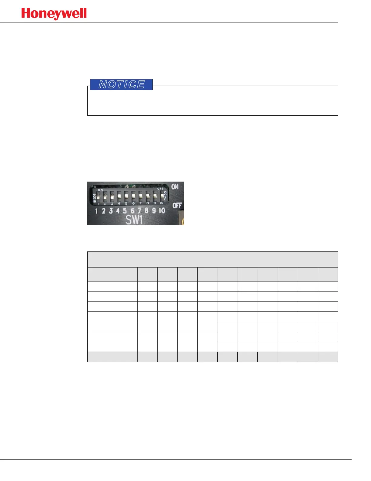
DIP Switch SW1
The digital address for RS-485 communication can be set using positions 4 through
10 on DIP switch SW1, shown in Figure 24. (Do not change switch positions 1, 2, or
3 on SW1; they are for factory use only.)
Figure 24. Ten-position DIP switch SW1.
SW1 Configuration
Digital Address 1 2 3 4 5 6 7 8 9 10
000 off off off off off off off off off off
001 off off off off off off off off off on
002 off off off off off off off off on off
003 off off off off off off off off on on
124 off off off on on on on on off off
125 off off off on on on on on off on
126 off off off on on on on on on off
127 (default) off off off on on on on on on on

 Loading...


